Tamp pad

a technology of tamping and printing ink, which is applied in the field of tamping, can solve the problems of difficult access with a tamping ink, and achieve the effects of reducing the number of tampings, improving the appearance of the entire surface, and improving the quality of the tamping ink

Inactive Publication Date: 2005-07-19
TELEFON AB LM ERICSSON (PUBL)
View PDF9 Cites 2 Cited by
  • Summary
  • Abstract
  • Description
  • Claims
  • Application Information

AI Technical Summary

Benefits of technology

[0009]As in the above described method to tamp print in three stages, also the rotating tamp pad can do the same; the tamp pad is provided with a convex bottom and concave sides and is compressed, so that the sides can print on the sides of the piece. Likewise, the rotating tamp pad can be provided with projections and recesses for enabling printing on least accessible places on the piece. It can also be provided with aeration channels for ventilating away air accumulations described above. By the method of a form adapted tamp pad provided with recesses it will become possible to tamp print on parts of and / or entire pieces equipped with complicated details, such as corners, hole means and projections. In comparison with other methods, the most important advantages with the invention is that the method is much cheaper and faster and gives a result which is improved in form of entirely covered surfaces even on complicated parts of the piece with a reduced number of tamp printings. With this method the piece does not need to be tamp printed several times from several directions for covering all surfaces of the piece.

Problems solved by technology

This means that the ink is not prevented by the air accumulation to reach the corner and other places which otherwise would be difficult to access.
In the irregularities of a piece it may be difficult to access with a tamp pad with printing ink.

Method used


Image

  • Tamp pad
  • Tamp pad
  • Tamp pad

Examples


first embodiment

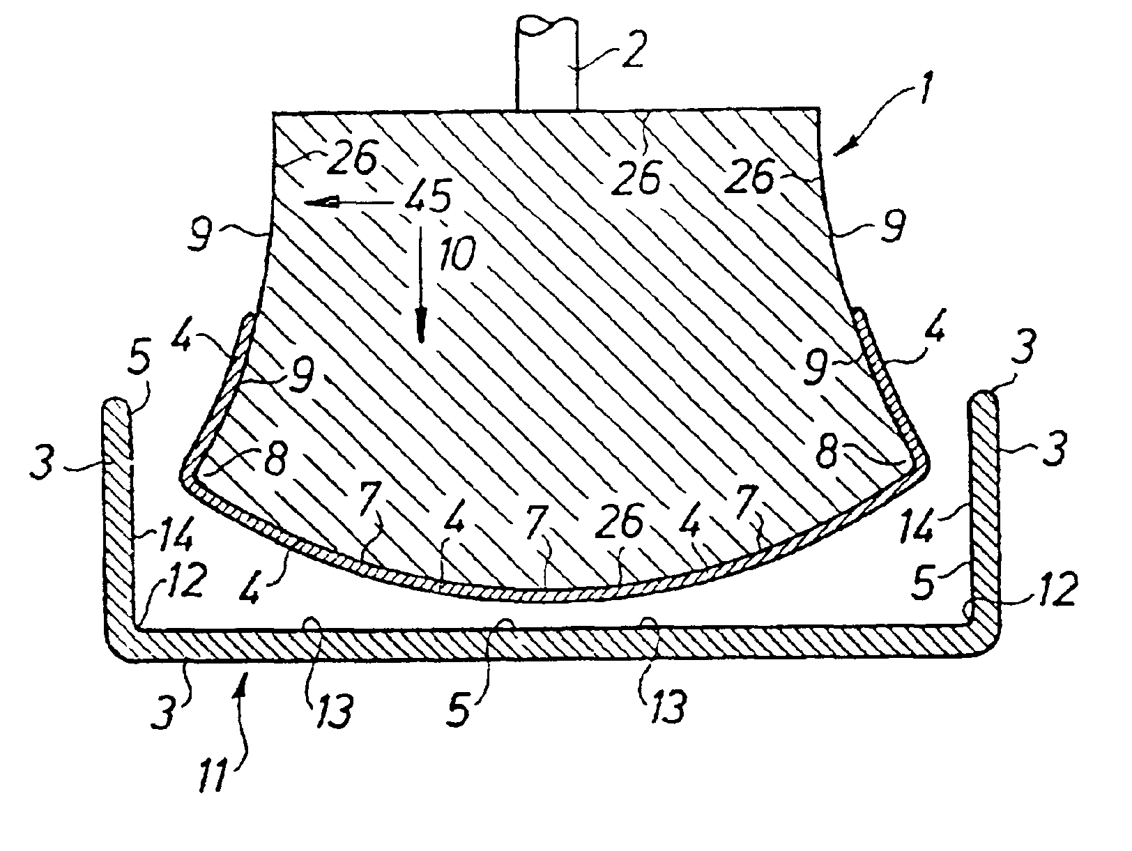
[0017]A first stage in a tamp printing method is shown in FIG. 1, the device according to the invention having a tamp pad 1, which is formed of a soft material, preferably silicon, and which is moving generally in a direction 10. The pad is attached to an attachment device 2 of a tamp printing machine, a picture 4, which preferably consists of one colour containing metal fragments for being electrically conductive, being fetched from a printing block, whereafter it shall be printed on a piece 3, for example on an inside 5 of a mobile telephone cover 11. The tamp pad 1 has a number of external boundary surfaces 26, at least one such surface being a side 7, which has a convex form, and neighbouring boundary surfaces, which form corners 8, and at least two concave sides 9. The piece 3 has at its inside 5 corners 12, a bottom 13 and at least two sides 14.

[0018]A second stage of the tamp printing method is shown in FIG. 2. When the side 7 of the tamp pad 1 has approached the bottom 13 of...

second embodiment

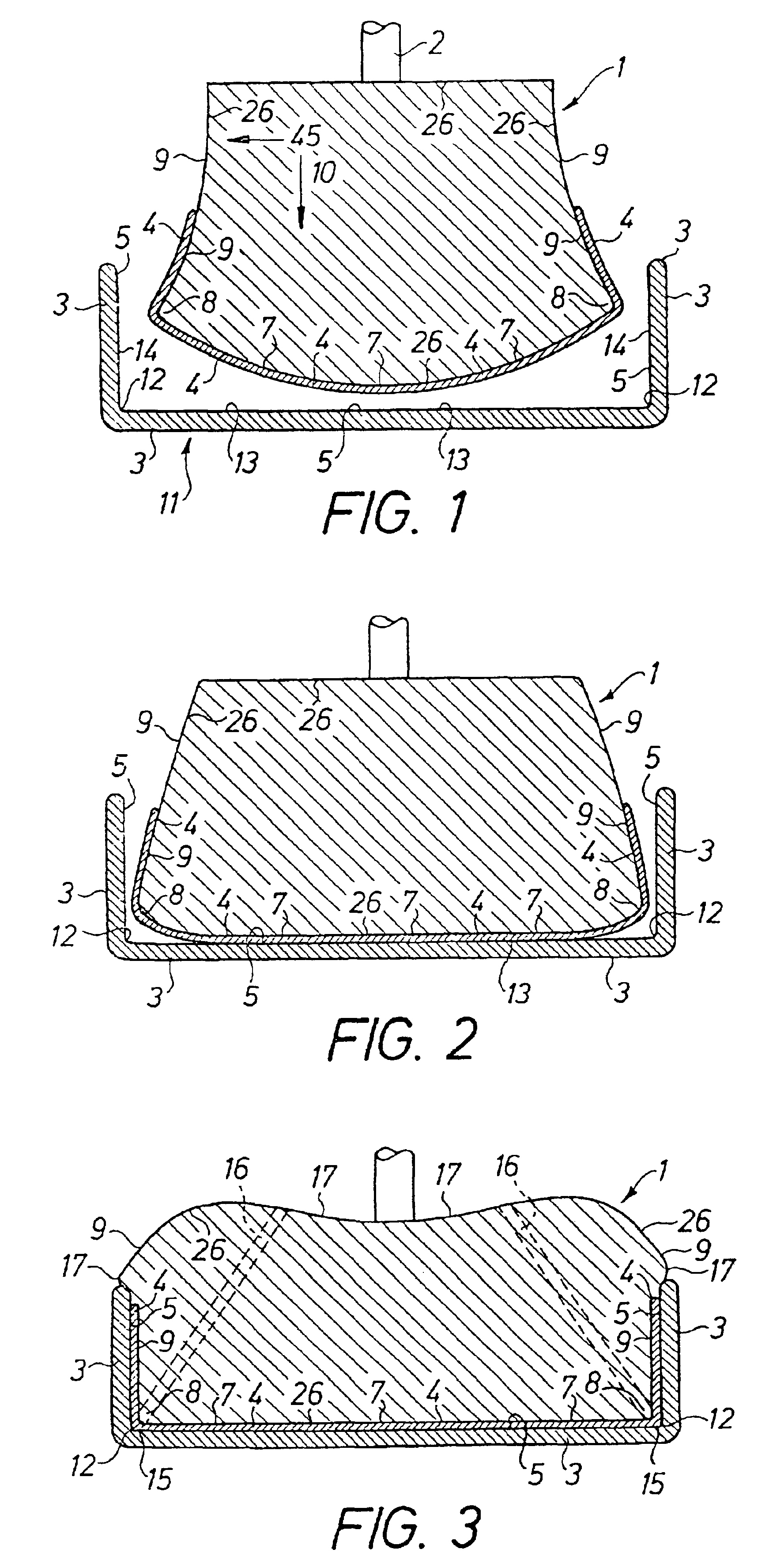
[0020]a tamp pad 18 is shown in FIG. 4. This pad 18 is provided with at least a number of concave sides 19 and a number of convex sides 20 and is shown in stage one according to FIG. 1. According to the invention it is possible to tamp print on a substrate with more than one bottom 13 and more than two sides 14 in the same process generally in one direction 10. Then also convex corners can be tamp printed. Also in this embodiment all corners may need to be aired through aeration channels 23, as has been described above. The picture 4 is transferred in accordance with the three stages as has been described above to the inside of the piece 21.

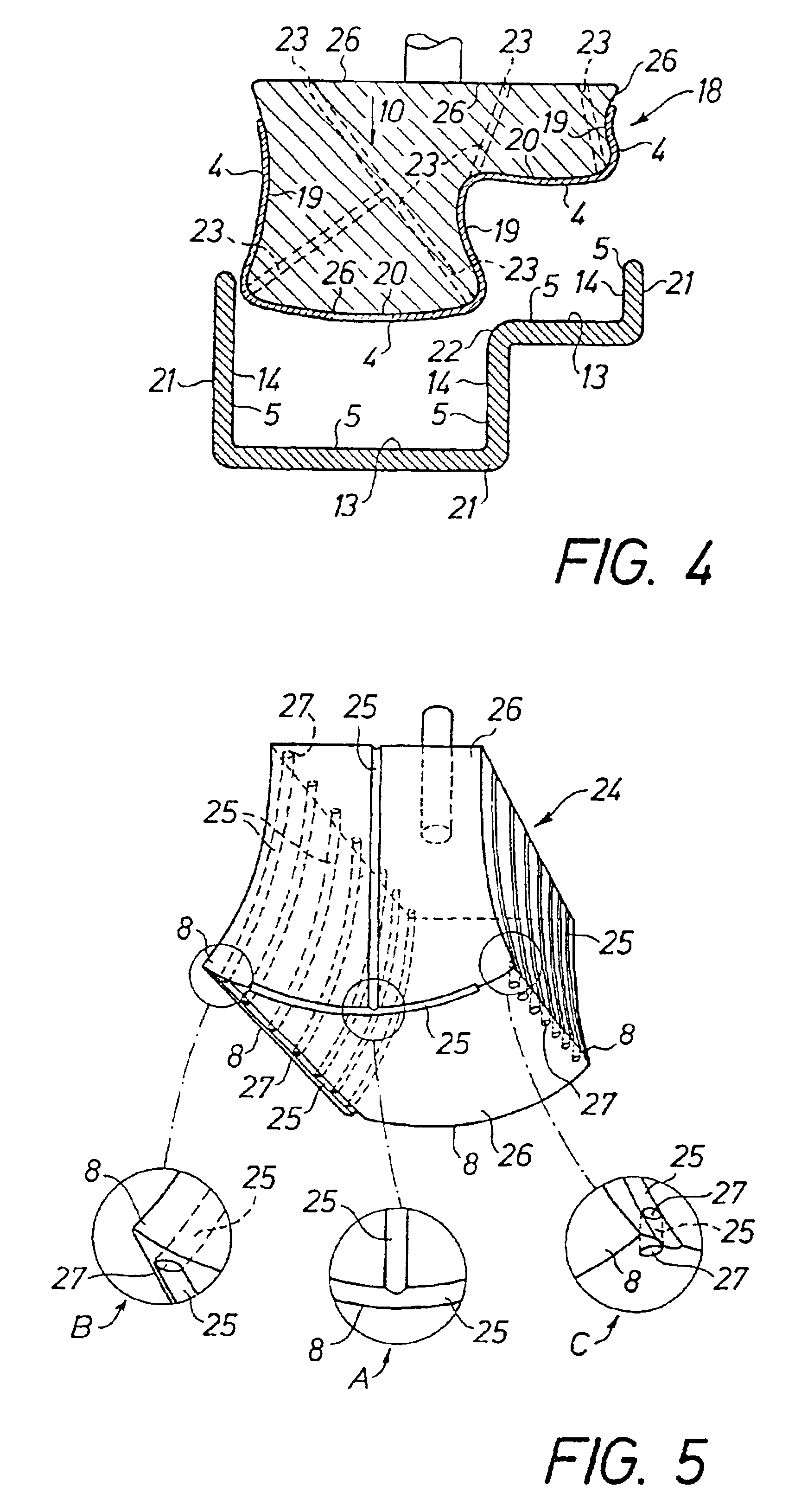
[0021]A tamp pad 24 is shown in perspective in FIG. 5. This pad 24 show examples of different types of aeration channels 25, which have the purpose of ventilating away the air accumulations 15 mentioned in relation to FIG. 3 above. These channels can be designed as aeration channels 25 arranged in the outer boundary surface 26 of the tamp pad 24 ...


PUM


Abstract

Tamp printing of at least one picture (4) occurs by means of at least one tamp pad (1, 18, 24, 34) on a piece (3), which has boundary surfaces (5, 13) forming angles relative to each other, the tamp pad first printing in one direction (10) against a boundary surface (13, 43) and thereafter, after further compression of the tamp pad (1) against said boundary surface (13) due to its deformation, prints in another direction (45) than the direction (10) against another boundary surface or other boundary surfaces (5, 43), whereby the picture is transferred to said boundary surfaces.

Description

[0001]This application is a divisional of application Ser. No. 09 / 467,535, filed on Dec. 20, 1999 now U.S. Pat. No. 6,244,172. This application claims priority from Swedish Patent Application No. 9804539.6, filed on Dec. 21, 1998.FIELD OF THE INVENTION[0002]The present invention relates to a device and a method at a tamp pad and at tamp printing intended to simplify the printing method, in which ink is applied on a tamp pad, that prints a picture on a piece having concave sides and a convex bottom, wherein the tamp pad has a shape in conformity with the piece for printing on the bottom and sides of the piece and can be provided with channel means for conveying away air accumulated between the piece and the tamp pad, so that the ink can be applied on surfaces difficult to access.BACKGROUND OF THE INVENTION[0003]In designs of this kind appearing on the market it is possible by means of a method called tamp printing to transfer a picture to a piece on surfaces which are only slightly c...

Claims


Application Information

Patent Timeline
Patent Type & Authority Patents(United States)
IPC IPC(8): B41M1/40B41F17/00H05K9/00
CPCB41F17/006B41M1/40H05K9/0022H05K9/0045
Inventor HOLMBERG, PERERIKSSON, LARS
Owner TELEFON AB LM ERICSSON (PUBL)
Why Eureka
Try Eureka