Ceiling Fan, Hanger Assembly of the Ceiling Fan, and Mounting Bracket of the Hanger Assembly

a technology for ceiling fans and mounting brackets, which is applied in the direction of non-positive displacement fluid engines, pump components, liquid fuel engine components, etc., can solve the problems of high failure rate of ceiling fans and heavy ceiling fans, and prolong the service life of ceiling fans, so as to reduce the failure rate of ceiling fans and effectively prevent the shaking of stators during the initialization process. , the effect of prolonging the service li

Active Publication Date: 2017-07-20
SUNONWEALTH ELECTRIC MACHINE IND
View PDF4 Cites 9 Cited by
  • Summary
  • Abstract
  • Description
  • Claims
  • Application Information

AI Technical Summary

Benefits of technology

[0048]Based on the above structure, through the arrangement of the receiving portions on the two lateral walls of the mounting bracket, the two ends of the coupling rod can be respectively received in the receiving portions of the two lateral walls. In this regard, the coupling rod can only rotate in the receiving portions without pivoting about the axle parallel to the axial direction. Therefore, when the stator of the motor experiences the torque, the stator of the motor and the fan rod will not pivot about the axle parallel to the axial direction. Advantageously, shaking of the stator during the initialization process can be effectively prevented, prolonging the service life of the ceiling fan. Moreover, since the stator of the motor, the coupling rod and the fan rod will not pivot about the axle parallel to the axial direction, the lead wire in the wire groove, the channel and the shaft tube will not get twisted and become damaged. Therefore, the failure rate of the ceiling fan can be reduced.

Problems solved by technology

However, the ceiling fan is usually heavy.
As a result, the lead wire W can be twisted apart under the twisting force, leading to a high failure rate of the ceiling fan.

Method used


Image

  • Ceiling Fan, Hanger Assembly of the Ceiling Fan, and Mounting Bracket of the Hanger Assembly
  • Ceiling Fan, Hanger Assembly of the Ceiling Fan, and Mounting Bracket of the Hanger Assembly
  • Ceiling Fan, Hanger Assembly of the Ceiling Fan, and Mounting Bracket of the Hanger Assembly

Examples


Embodiment Construction

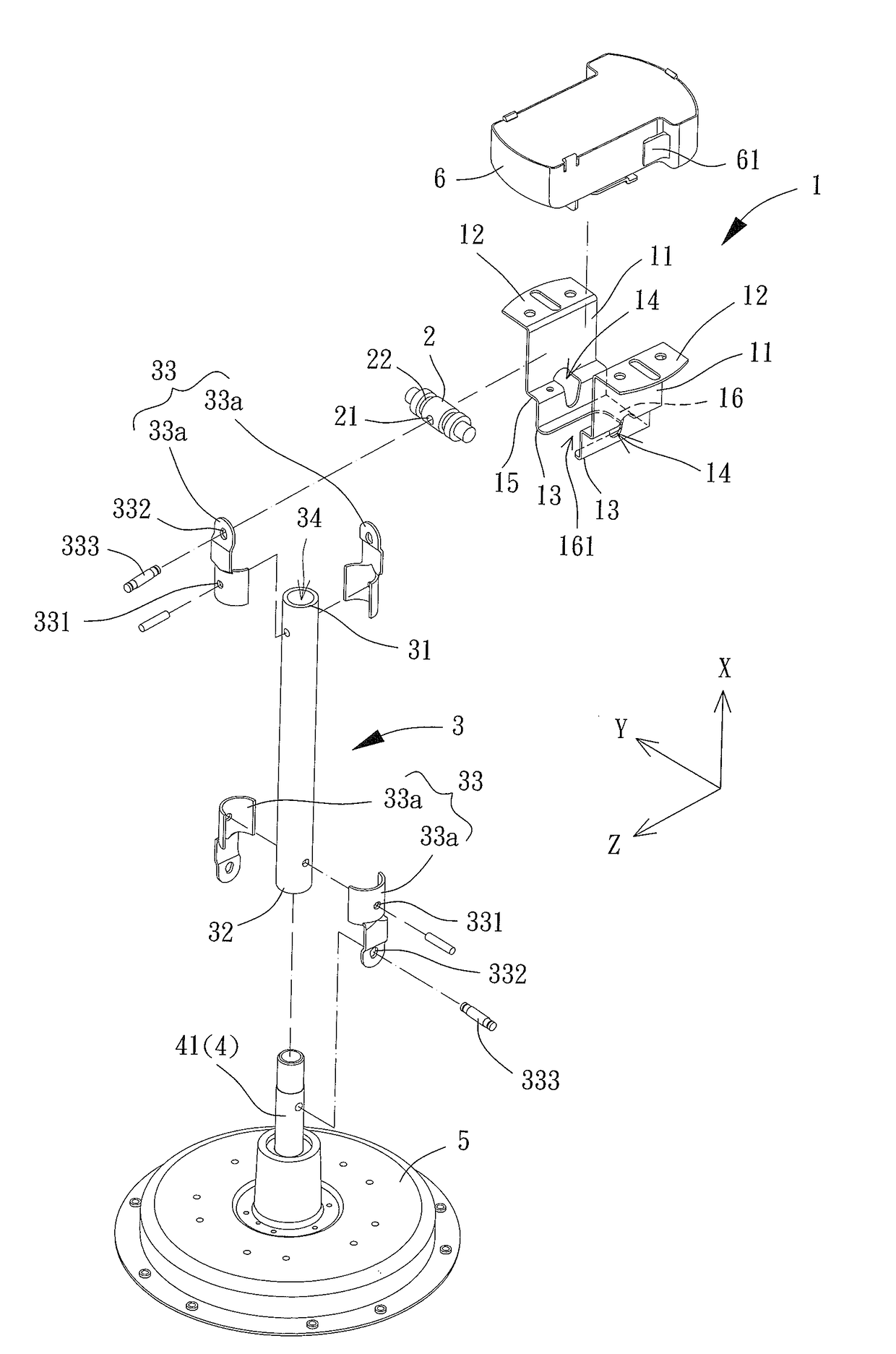
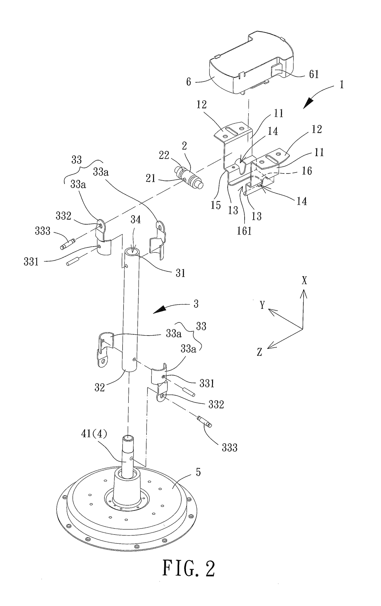
[0066]FIG. 2 is an exploded view of a hanger assembly of a ceiling fan according to an embodiment of the disclosure. The hanger assembly includes a mounting bracket 1, a coupling rod 2 and a fan rod 3. The coupling rod 2 is coupled with the mounting bracket 1. The fan rod 3 is coupled with the coupling rod 2.

[0067]The mounting bracket 1 includes two lateral walls 11. Each of the two lateral walls 11 includes a mounting end 12 and a hanger end 13 spaced from each other in an axial direction X. The two lateral walls 11 are opposite to each other in a first direction Y perpendicular to the axial direction X. The mounting end 12 may be mounted to a predetermined structure such as the ceiling of a building. Each of the two lateral walls 11 further includes a receiving portion 14 spaced from the hanger end 13 in the axial direction X, such that the receiving portion 14 is located between the hanger end 13 and the mounting end 12. In addition, the receiving portions 14 of the two lateral w...


PUM


Abstract

A ceiling fan, a hanger assembly of the ceiling fan, and a mounting bracket of the hanger assembly are designed with a lower failure rate. The hanger assembly of the ceiling fan includes a coupling rod and a fan rod. The mounting bracket has two lateral walls opposing to each other. Each of the two lateral walls includes a mounting end, a hanger end and a receiving portion. The coupling rod has two ends respectively received in the receiving portions of the two lateral walls. The fan rod has a first end coupled with the coupling rod, as well as a second end coupled with a stator of a motor of the ceiling fan.

Description

CROSS REFERENCE TO RELATED APPLICATIONS[0001]The application claims the benefit of Taiwan application serial No. 105101573, filed on Jan. 19, 2016, and the subject matter of which is incorporated herein by reference.BACKGROUND OF THE INVENTION[0002]1. Field of the Invention[0003]The present disclosure generally relates to a ceiling fan, a hanger assembly of the ceiling fan, and a mounting bracket of the hanger assembly and, more particularly, to a hanger assembly having a mounting bracket to which a coupling rod is pivotally coupled, as well as a ceiling fan having the hanger assembly.[0004]2. Description of the Related Art[0005]FIG. 1 shows a hanger assembly 9 of a conventional ceiling fan. The hanger assembly 9 includes a mounting bracket 91, a bracket-coupling portion 92 and a fan rod 93. The bracket-coupling portion 92 is coupled with the mounting bracket 91, and the fan rod 93 can be coupled with the bracket-coupling portion 92. The mounting bracket 91 can be fixed to the ceili...

Claims


Application Information

Patent Timeline
Patent Type & Authority Applications(United States)
IPC IPC(8): F04D25/08F04D25/06F04D29/60
CPCF04D25/088F04D25/06F04D29/601F04D29/002F04D25/0693
Inventor HORNG, ALEXYIN, TSO-KUOSHAN, DUO-NIAN
Owner SUNONWEALTH ELECTRIC MACHINE IND
Why Eureka
Try Eureka