
Confidence Estimation For Optical Flow Under Low Light Conditions

Active Publication Date: 2017-07-20
TEXAS INSTR INC
View PDF1 Cites 5 Cited by
  • Summary
  • Abstract
  • Description
  • Claims
  • Application Information

AI Technical Summary

Benefits of technology

The patent describes a way to estimate the score or measure of optical flow in a video. It generates a map that shows the confidence levels or weights for each pixel in the video. This helps higher level algorithms to assign less importance to areas of the video that have poor optical flow.

Problems solved by technology

In low light or low texture regions, the flow vector may be incorrect.

Method used


Image

  • Confidence Estimation For Optical Flow Under Low Light Conditions
  • Confidence Estimation For Optical Flow Under Low Light Conditions
  • Confidence Estimation For Optical Flow Under Low Light Conditions

Examples


Embodiment Construction

[0015]This invention shows a dense optical flow estimation algorithm using a quasi-parametric approach, capable of accurate, highly precise and efficient optical flow estimation over a large range of relative pixel motions.

[0016]While there has been optical flow algorithms developed in the prior art, there has not been an attempt to generate a confidence map in real time, along with the optical flow. The estimated confidence map helps to understand which of the flow values are correct and which of them are potentially wrong.

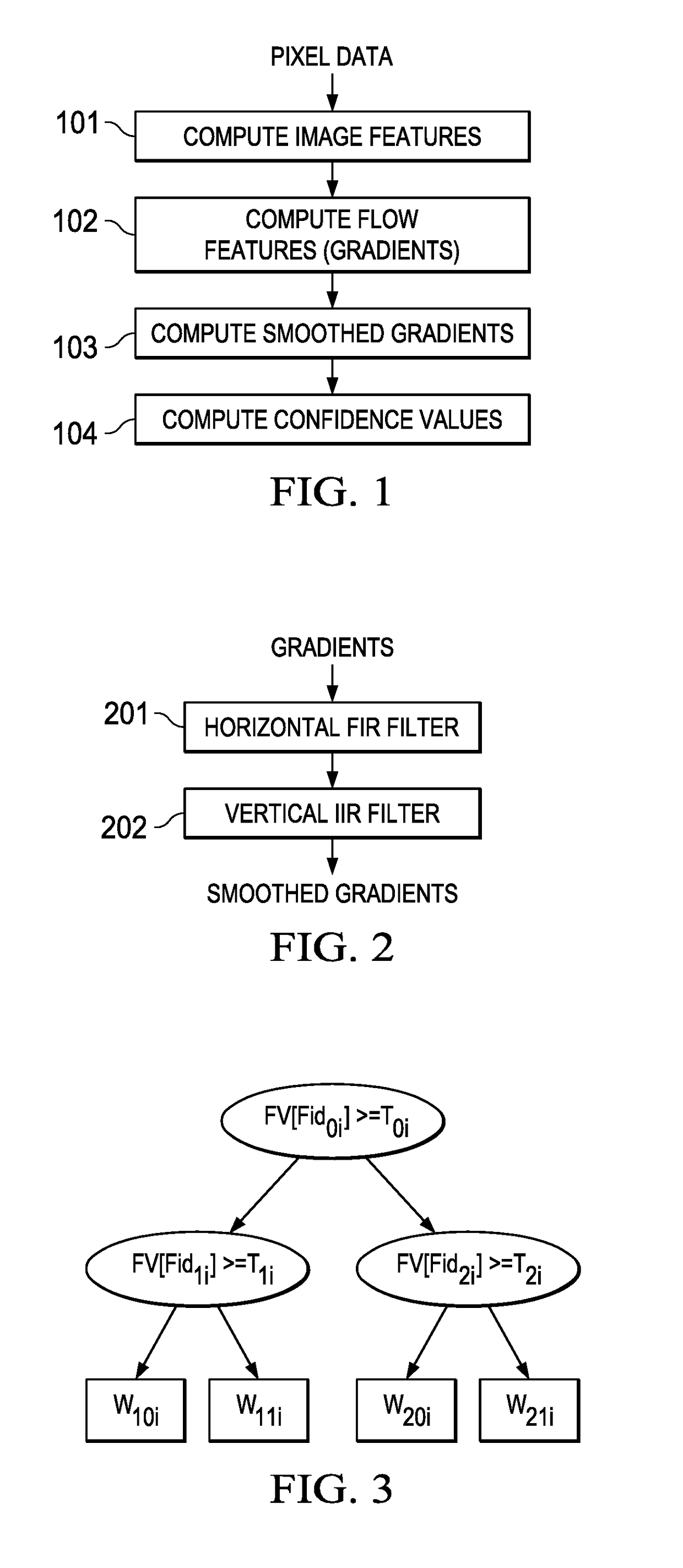
[0017]The described optical flow confidence map generation algorithm shown on FIG. 1 is implemented as follows:

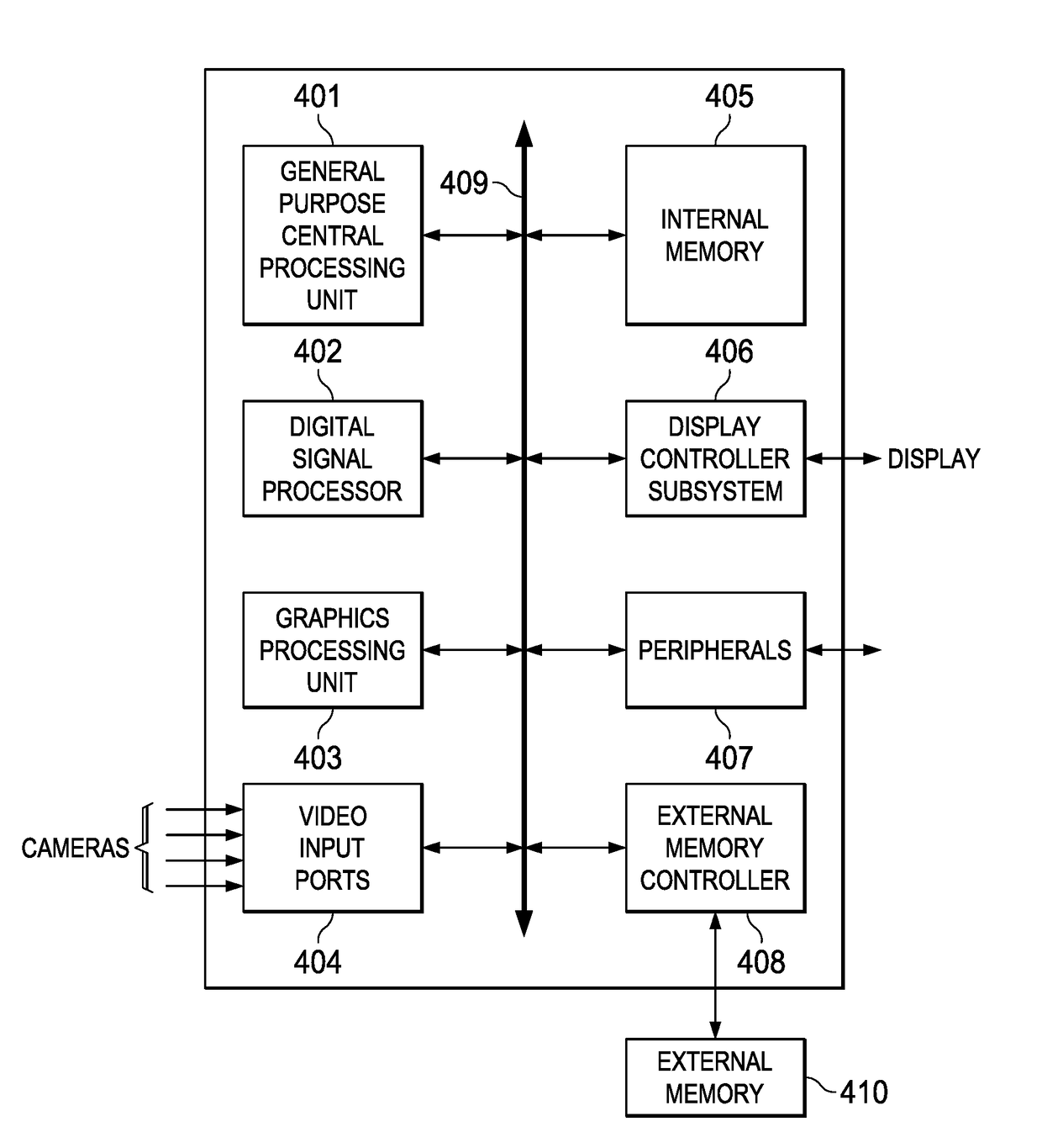
[0018]For every pixel, a set of features are computed. The features include image features 101 and flow features 102. Smoothened versions 103 of the features are also computed.

[0019]These features are sent to a decision tree classifier 104 that outputs a classifier score. This classifier score is then converted to a confidence value.

[0020]The features us...


PUM


Abstract

A confidence map for optical flow gradients is constructed calculating a set of census texture gradients for each pixel of an image, filtering said gradients and extracting confidence values from said gradients using a plurality of decision tree classifiers. A confidence map is then generated from said confidence values.

Description

CLAIM OF PRIORITY[0001]This application claims priority under 35 U.S.0 119(e)(1) to Indian Provisional Application No. 201641001331 filed Jan. 14, 2016TECHNICAL FIELD OF THE INVENTION[0002]The technical field of this invention is optical flow estimation.BACKGROUND OF THE INVENTION[0003]Optical flow or optic flow is the pattern of apparent motion of objects, surfaces, and edges in a visual scene caused by the relative motion between an observer (an eye or a camera) and the scene. The concept of optical flow was introduced by the American psychologist James J. Gibson in the 1940s to describe the visual stimulus provided to animals moving through the world. Subsequently the term optical flow has been co-opted in the computer vision domain to describe pixel motion in between two temporally ordered images of the scene, and incorporate related techniques of estimation of pixel motion. The optical flow estimation techniques are further integrated in related techniques of image processing a...

Claims


Application Information

Patent Timeline
IPC IPC(8): G06T7/20G06K9/62G06T5/00G06K9/48G06V10/764
CPCG06T7/2066G06K9/481G06T7/2033G06T5/002G06K9/6282G06T2207/30252G06T7/215G06T7/269G06V20/56G06V10/443G06V10/764G06F18/24323G06T7/246G06T5/70
Inventor MATHEW, MANUGARUD, HRUSHIKESH TUKARAMNAGORI, SOYEB NOORMOHAMMED
Owner TEXAS INSTR INC
Learn More