
Cavity filter including ceramic resonator

a ceramic resonator and cavity filter technology, applied in the field of cavity filters, can solve the problem that the shape modification of the coaxial resonator cannot meet the demands of small siz

Inactive Publication Date: 2017-07-20
ACE TECH
View PDF3 Cites 8 Cited by
  • Summary
  • Abstract
  • Description
  • Claims
  • Application Information

AI Technical Summary

Benefits of technology

This patent aims to provide a tiny filter made of ceramic that can be created in a compact way.

Problems solved by technology

However, such modification of the shape of the coaxial resonator can no longer satisfy the demands for smaller size as required in current base stations.

Method used


Image

  • Cavity filter including ceramic resonator
  • Cavity filter including ceramic resonator
  • Cavity filter including ceramic resonator

Examples


Embodiment Construction

[0035]As the invention allows for various changes and numerous embodiments, particular embodiments will be illustrated in the drawings and described in detail in the written description. However, this is not intended to limit the present invention to particular modes of practice, and it is to be appreciated that all changes, equivalents, and substitutes that do not depart from the spirit and technical scope of the present invention are encompassed in the present invention.

[0036]While such terms as “first” and “second,” etc., may be used to describe various components, such components must not be limited to the above terms. The above terms are used only to distinguish one component from another. For example, a first component may be referred to as a second component without departing from the scope of rights of the present invention, and likewise a second component may be referred to as a first component. Certain embodiments of the invention will be described below in more detail wit...


PUM


Abstract

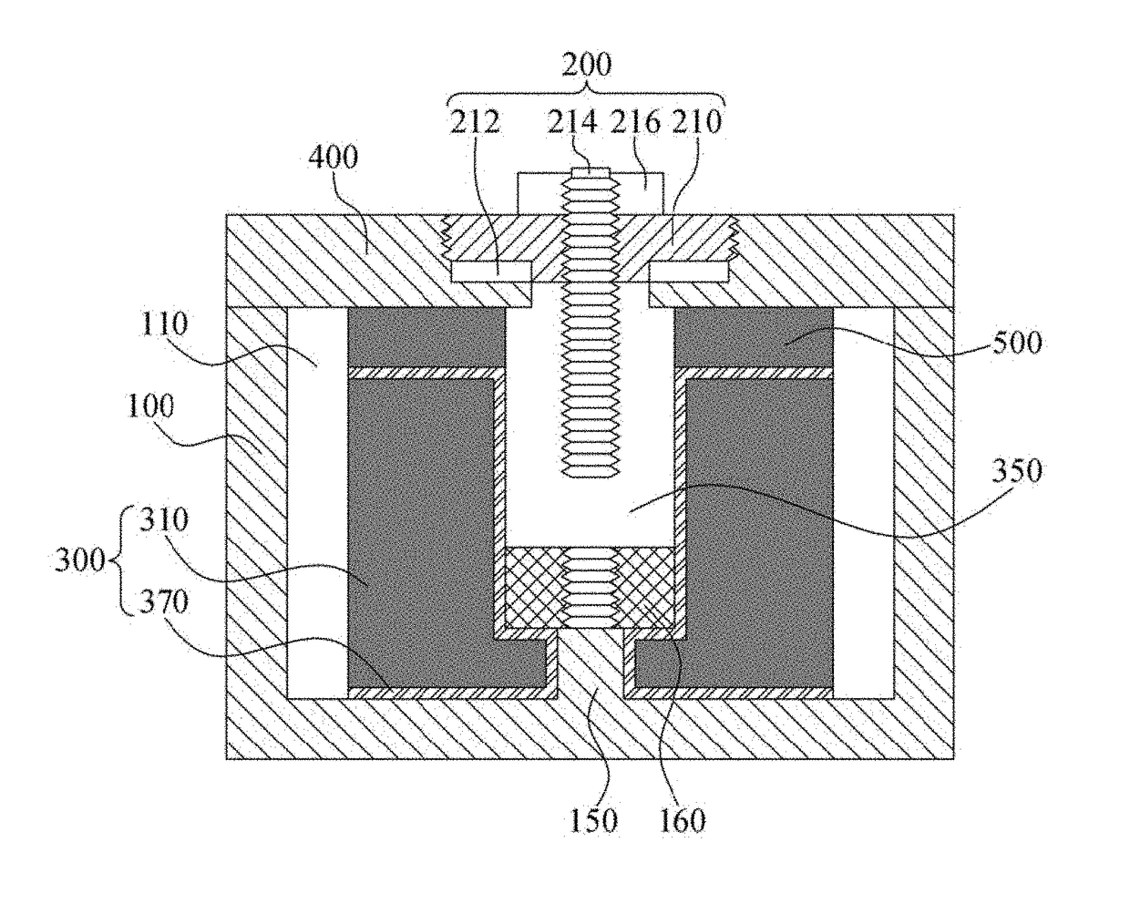
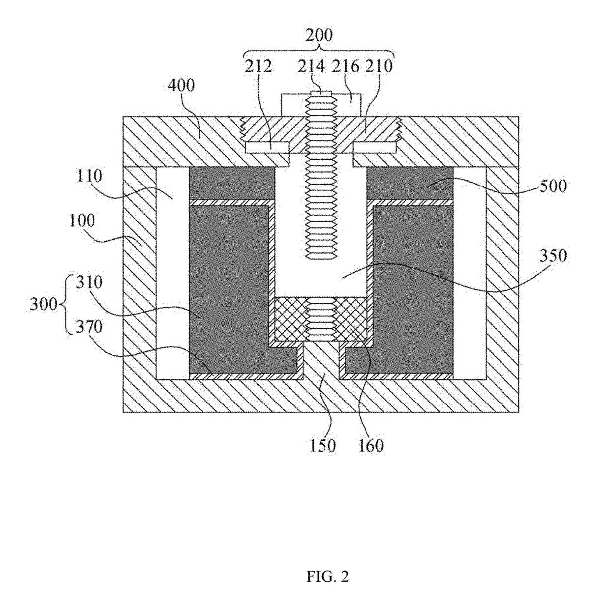
A cavity filter having a ceramic resonator is disclosed. The disclosed cavity filter may include: a housing in which at least one cavity is formed and which has a ceramic resonator held in the cavity; a ceramic ring joined to an upper part of the ceramic resonator; and a cover joined to one side of the housing, where a through-hole is formed in the ceramic resonator to form a penetration from one side to the other side along one direction, and a metal layer is formed on a surface on the one side of the ceramic resonator, on a surface on the other side of the ceramic resonator, and on the inner perimeter of the through-hole. The disclosed cavity filter can provide the advantage that it can be manufactured as a compact structure.

Description

CROSS-REFERENCE TO RELATED APPLICATIONS[0001]This application claims the benefit of Korean Patent Application No. 10-2016-0006235, filed with the Korean Intellectual Property Office on Jan. 19, 2016, the disclosure of which is incorporated herein by reference in its entirety.BACKGROUND1. Technical Field[0002]The present invention relates to a cavity filter, more particularly to a cavity filter that includes a ceramic resonator.2. Description of the Related Art[0003]With advances in mobile communication, there have been rapid increases in demand for RF equipment such as filters, duplexers, multiplexers, and the like. RF equipment may be used in the filtering, separation, and transfer of signals in places such as base stations, etc., in a mobile communication system.[0004]An RF filter is a device for passing the signals of a particular frequency band. In devices that require high power, such as in the base station of a mobile communication system, a cavity filter having a cavity-based...

Claims


Application Information

Patent Timeline
IPC IPC(8): H01P1/207
CPCH01P1/207H01P1/2084H01P1/205H01P7/10
Inventor YOON, JAE KWANGCHUN, DONG-WAN
Owner ACE TECH
Learn More