Method Of, And Transceiver Station And Mobile Terminal For, Distributing System Information In A Cellular Telecommunications Network

Active Publication Date: 2017-07-20
NEDERLANDSE ORG VOOR TOEGEPAST-NATUURWETENSCHAPPELIJK ONDERZOEK (TNO)
View PDF25 Cites 10 Cited by
  • Summary
  • Abstract
  • Description
  • Claims
  • Application Information

AI Technical Summary

Benefits of technology

[0010]Further advantage is achieved by enabling the possibility to use the same system information for different data cells. In that case, pointers associated with such data cells may simply designate a same system information block, or as described herein the group system information block. Terminals in these data cells automatically obtain the commonly identical system information. This saves energy and resources on the side of the signaling cell.
[0011]Even more sophisticated embodiments are possible, for example in case only a part of the system information for such data cells would be identical while other parts would be unique for each data cell. In that case, the common indicator channel for these data cells may designate the group system information block. The group system information block comprising the common system information, may additionally include a pointer to unique system information resources for each data cell or a pointer to a further specific indicator channel. The solution of the present invention may thus be tailored to many different situations.
[0012]Therefore, in accordance with an embodiment, at least part or all of system information data to be sent via said system information blocks is identical for a plurality of said data cells, i.e. a group of data cells, wherein said step of transmitting comprises transmitting a group system information block including said identical common system information data for the plurality of data cells.
[0013]In accordance with yet another embodiment, prior to said transmitting the method comprises: determining, by said signaling cell, a number of system information blocks required to be transmitted, and assigning, by said signaling cell, transmission capacity for transmitting the common indicator channel, wherein the transmission capacity is dynamically assigned in size dependent on said number of system information blocks determined. This enables the common indicator channel to be dynamic in size, dependent on the number of active data cells. If no data cells are active in the whole first coverage area of the signaling cell, then the size of the common indicator channel will be zero, i.e. no common indicator channels may be present. If, however, there are f

Problems solved by technology

Firstly because only those D-cells are active that need to be active at a particular moment in time.
However, the D-cells are

Method used


Image

  • Method Of, And Transceiver Station And Mobile Terminal For, Distributing System Information In A Cellular Telecommunications Network
  • Method Of, And Transceiver Station And Mobile Terminal For, Distributing System Information In A Cellular Telecommunications Network
  • Method Of, And Transceiver Station And Mobile Terminal For, Distributing System Information In A Cellular Telecommunications Network

Examples


Embodiment Construction

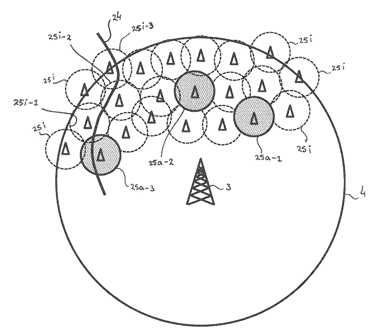
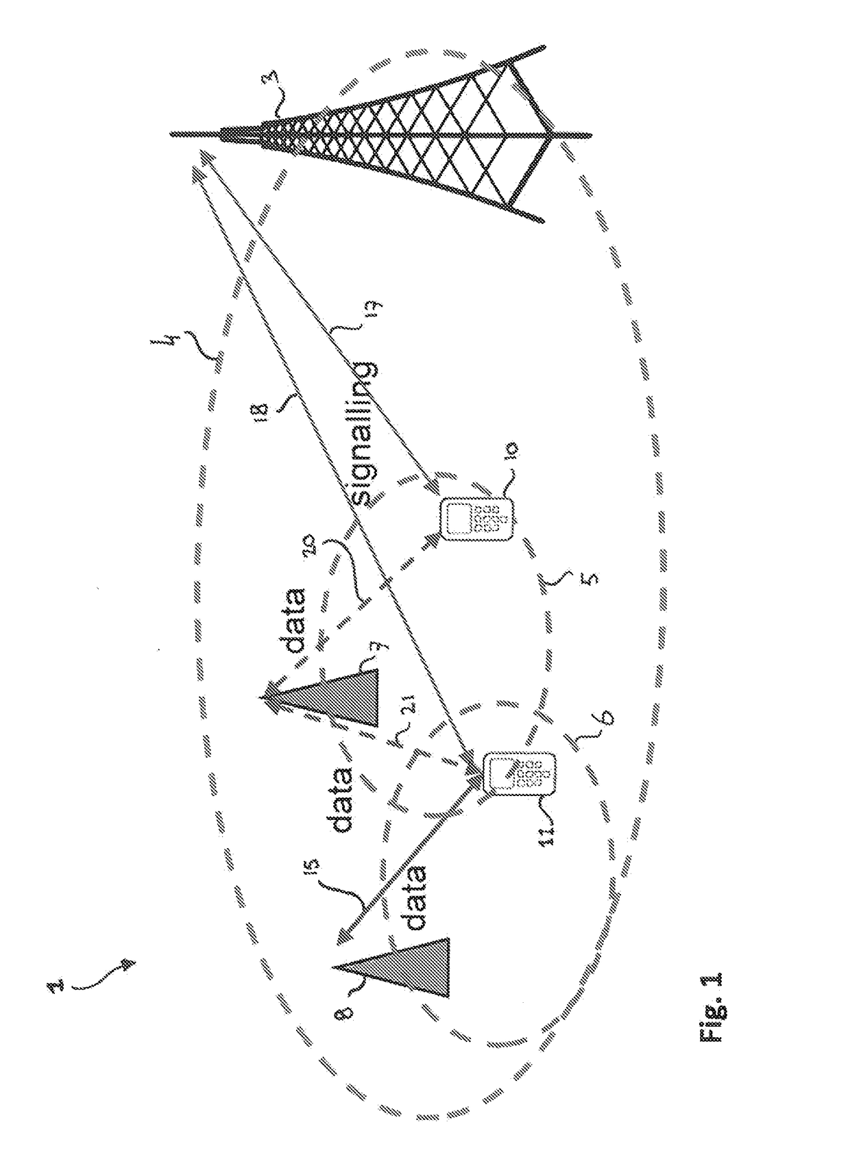
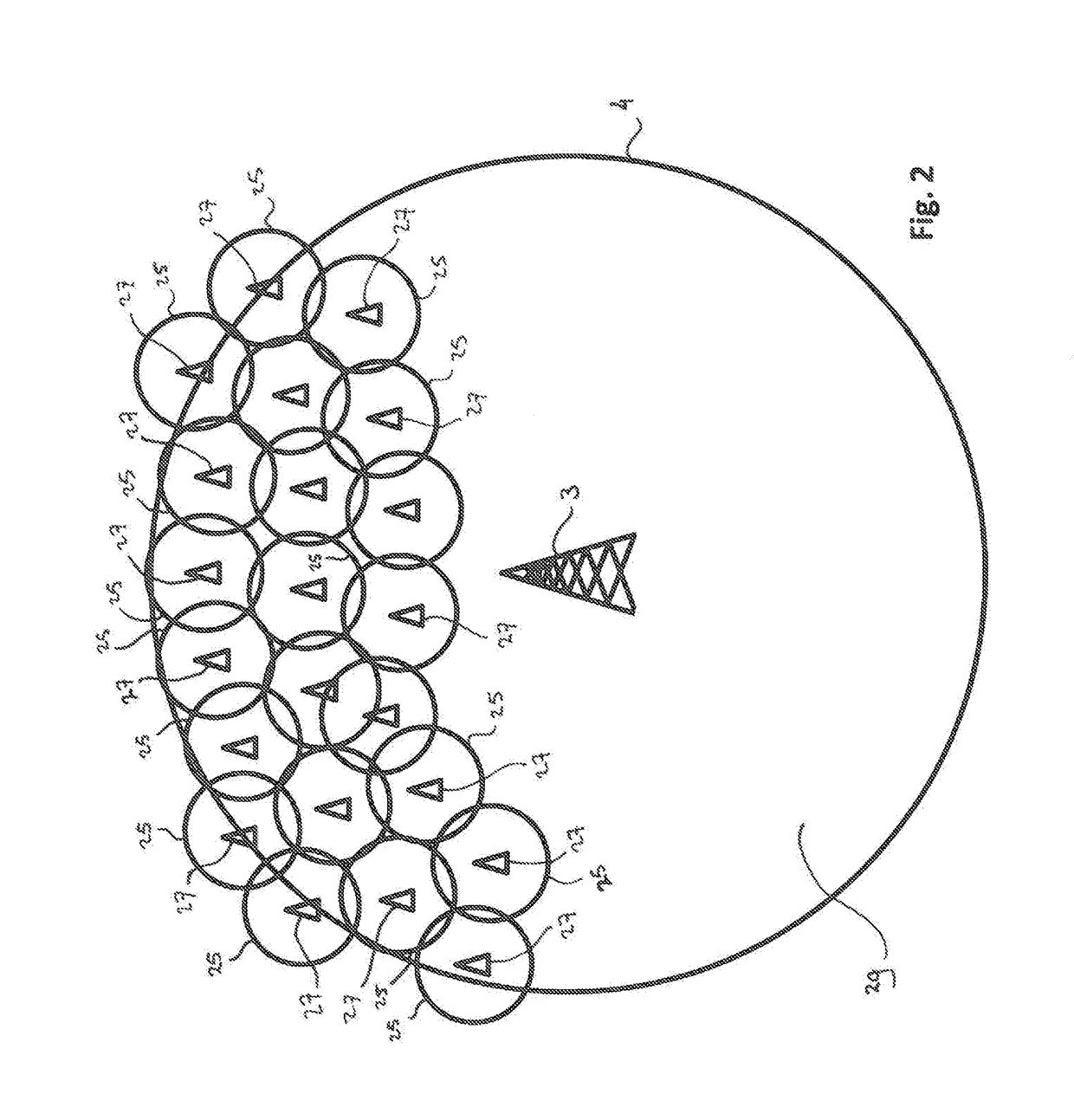
[0029]FIG. 1 schematically illustrates an access network 1 in a beyond cellular green generation (BCG2) type network. The BCG2 network is a design of an energy efficient cellular wireless network as being recently developed in a field of mobile communication. The access network 1 consists of various transceiver stations providing signaling cells, of which in FIG. 1 only one signaling cell transceiver station 3 is shown to enable explaining the principles of operation. In reality, the BCL2 network may comprise many access points such as the one illustrated in FIG. 1.

[0030]The transceiver station 3 typically serves a coverage area 4. The area 4 will hereinafter be referred to as the S-cell 4. The term ‘S-cell’ refers to a signaling cell and indicates the main functionality of the S-cell 4. For example, the S-cell 4 may exchange signaling messages with mobile terminals 10 and 11 in the network.

[0031]A further type of cells is provided by the data cells or D-cells, such as data cells 5 ...


PUM


Abstract

The invention is directed at a method of distributing system information to one or more mobile terminals in a cellular telecommunications network. The network comprises at least one signaling cell serving a first coverage area, and one or more data cells associated with said signaling cell, each one of said data cells serving a respective partial coverage area covering at least a part of the first coverage area. For each one of said data cells, the respective data cell is operated in either an active or inactive communication mode depending on whether there is at least one of said mobile terminals present in the partial coverage area of said respective data cell, and whether said at least one mobile terminal operates in an active terminal mode and is not served by other data cells.

Description

FIELD OF THE INVENTION[0001]The present invention is directed at a method of distributing system information to one or more mobile terminals in a cellular telecommunications network, the network comprising at least one signaling cell serving a first coverage area, and one or more data cells associated with said signaling cell, each one of said data cells serving a respective partial coverage area covering at least a part of the first coverage area; wherein, for each one of said data cells, said respective data cell is operated in either an active or inactive communication mode depending on whether there is at least one of said mobile terminals present in the partial coverage area of said respective data cell, and whether said at least one mobile terminal operates in an active terminal mode. The invention is further directed at a transceiver station, a mobile terminal, and a computer program product.BACKGROUND[0002]The present document relates to energy efficient cellular wireless ne...

Claims


Application Information

Patent Timeline
IPC IPC(8): H04W52/02H04W36/00H04L5/00H04W48/08H04W48/12
CPCH04W52/0206H04W48/08H04W36/0072H04L5/0032H04W48/12Y02D30/70
Inventor ZHANG, HAIBINLJUPCO, JORGUSESKIBLUME, OLIVER
Owner NEDERLANDSE ORG VOOR TOEGEPAST-NATUURWETENSCHAPPELIJK ONDERZOEK (TNO)
Why Eureka
Try Eureka