Vaporizing assembly and vapor generating device

a technology of vaporizing assembly and generating device, which is applied in the direction of inhalators, ohmic resistance heating, tobacco, etc., can solve the problems of reducing the negative pressure adjacent to the ejection head, the wick method cannot control how much fluid is vaporized, and the entire wick requires a large amount of energy, etc.

Active Publication Date: 2017-07-27
FUNAI ELECTRIC CO LTD
View PDF3 Cites 83 Cited by
  • Summary
  • Abstract
  • Description
  • Claims
  • Application Information

AI Technical Summary

Benefits of technology

[0015]In some embodiments, an amount of negative pressure adjacent the ejection head is reduced by provid...

Problems solved by technology

The problem lies in that the vaporizing heater must be small enough to heat up extremely quickly, but yet have enough surface area to catch all fluid and fluid droplets that is being ejected onto it.
The wick method has no control of how much fluid is vaporized.
Heating the entire wick requires a large amount of energy and may result in degradation of the w...

Method used


Image

  • Vaporizing assembly and vapor generating device
  • Vaporizing assembly and vapor generating device
  • Vaporizing assembly and vapor generating device

Examples


Embodiment Construction

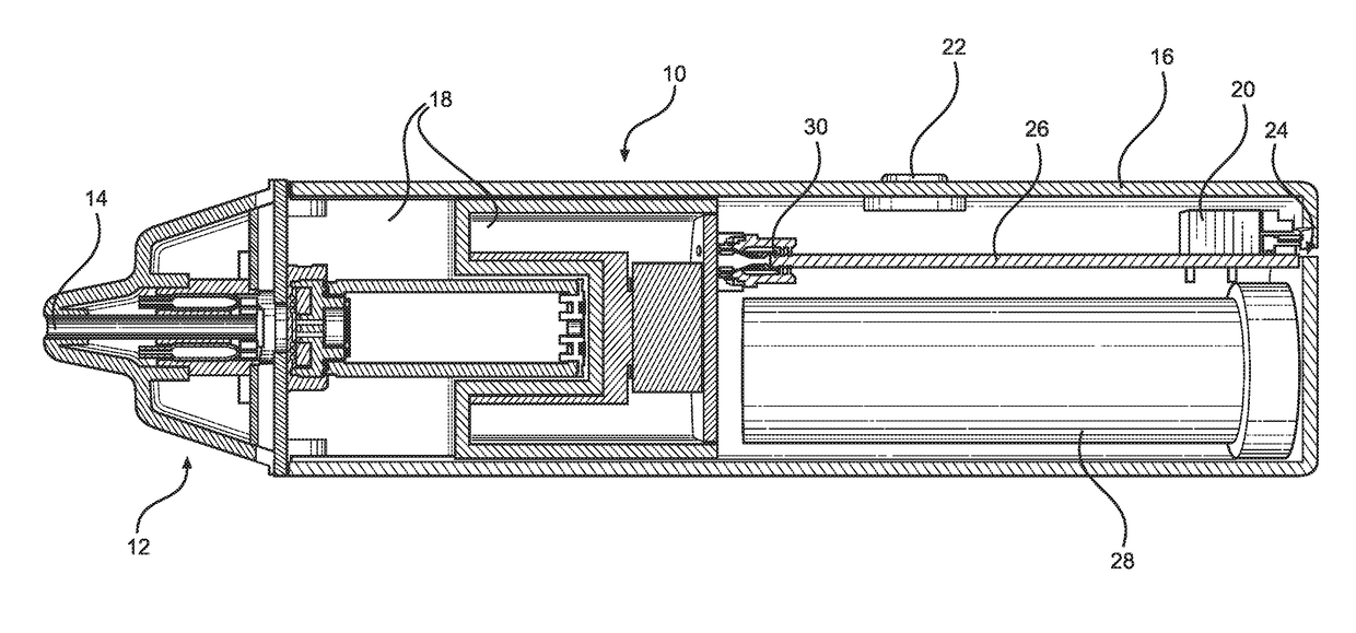
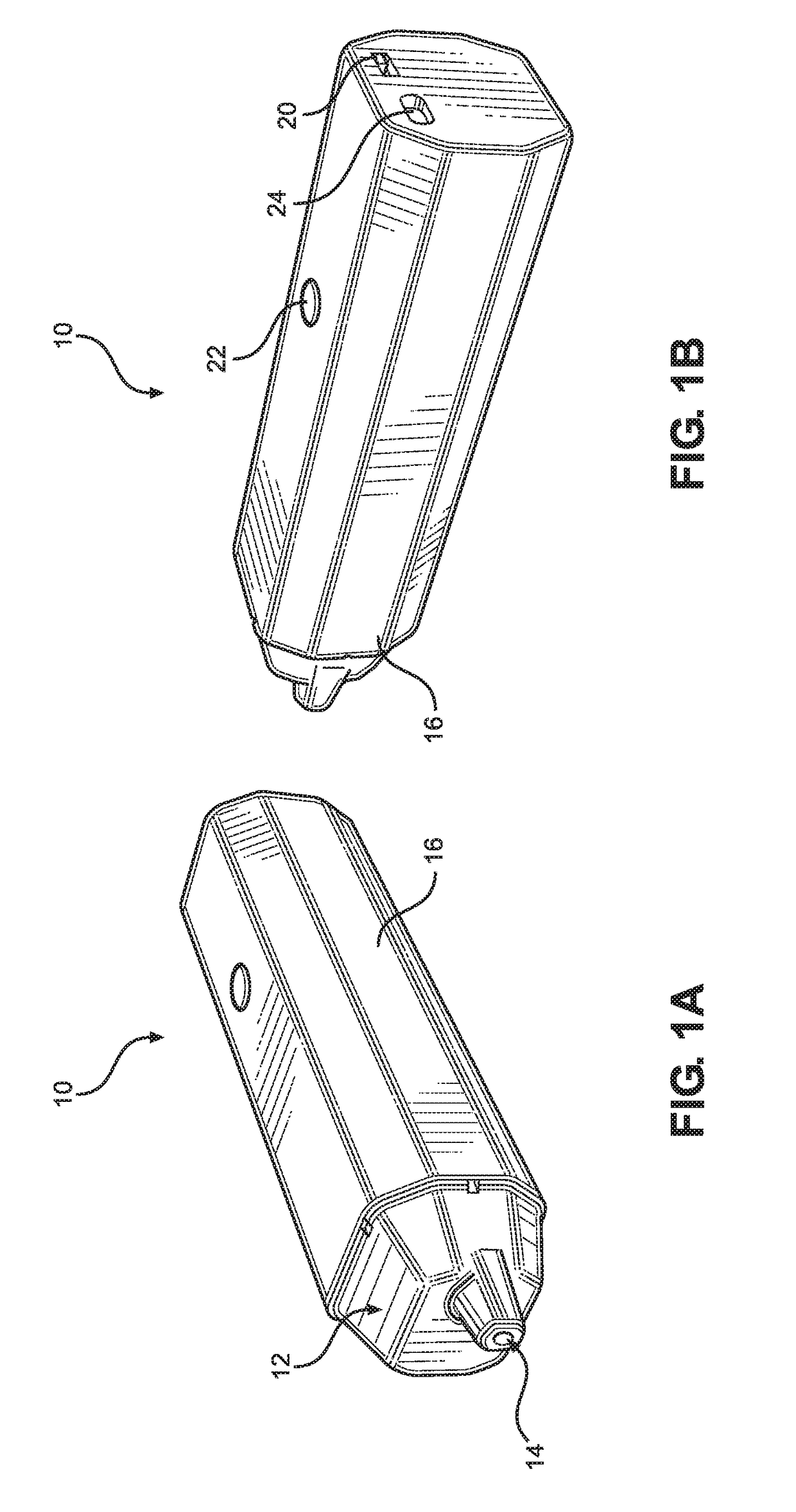
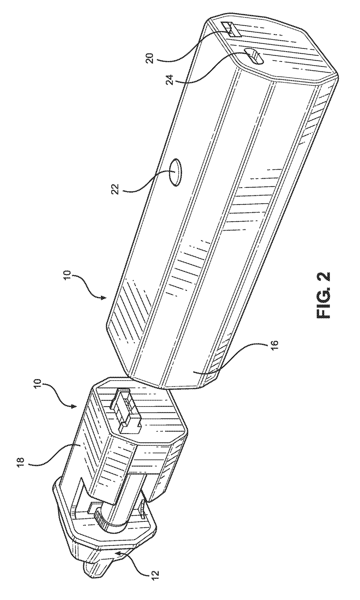
[0026]The disclosure is directed to a vaporizing device 10 as shown in FIG. 1 and components therefor as shown in FIG. 2. Such devices 10 may be used for a wide variety of applications wherein a liquid is ejected onto a vaporizing heater to provide a vapor stream as described in more detail below. Such devices 10 are typically hand held devices such as electronic cigarettes that have a mouthpiece 12 for inhaling vapors generated by the device 10. The mouthpiece 12 may include a vapor exit conduit 14 for flow of vapors out of the device 10. The main components of the device 10 include a housing body 16 and a removable vapor ejection assembly 18 (FIG. 2). The vaporizing device 10 typically includes a power switch 20, a vapor activation switch 22, and an alternative USB connection 24.

[0027]The mouthpiece 12, as well as the body 16 of the vaporizing device 10 may be made from a wide variety of materials including plastics, metals, glass, ceramic and the like provided the materials are c...


PUM


Abstract

A heater assembly for a vaporizing device, a vaporizing device containing the heater assembly, and a method for vaporizing fluid ejected by an ejection head. The heater assembly for the vaporizing device includes a vapor inlet end and a vapor outlet end, positive and negative electrodes for contact with positive and negative heater terminals on a vaporizing heater, an insulator disposed between the positive and negative electrodes, and a wick disposed between the insulator and the vaporizing heater for dispersion of liquid to be vaporized by the vaporizing heater and for back pressure control of the vaporizing device.

Description

RELATED APPLICATION[0001]This application claims priority to provisional application Ser. No. 62 / 281,804, filed Jan. 22, 2016.TECHNICAL FIELD[0002]One of the applications of a microfluidic ejection device is to jet a solution on to another device where a secondary function may be performed. A common secondary function is to vaporize a solution using a heater such that the contents of the solution can be vaporized so as to deliver the solution as a gaseous substance. Applications of such technology include, but are not limited to, metering and vaporizing device for electronic cigarettes, vapor therapy, gaseous pharmaceutical delivery, vapor phase reactions for micro-labs, and the like. This document discloses a method for integrating the fluid delivery and vaporization mechanisms into a single microfluidic device for the purposes of further miniaturization, higher precision vapor delivery and cost reduction, as well as operational efficiency.BACKGROUND AND SUMMARY[0003]When jetting a...

Claims


Application Information

Patent Timeline
IPC IPC(8): A24F47/00H05B1/02A24F40/10A24F40/44A24F40/46
CPCA24F47/008H05B2203/021H05B1/0244A61M15/06A61M11/042A61M15/025A24F40/46A24F40/10A24F40/44
Inventor ANDERSON, JR., JAMES D.VANDERPOOL, JASON
Owner FUNAI ELECTRIC CO LTD
Why Eureka
Try Eureka