Slide rail assembly and operation method thereof

Active Publication Date: 2017-07-27
KING SLIDE WORKS CO LTD +1
View PDF2 Cites 13 Cited by
  • Summary
  • Abstract
  • Description
  • Claims
  • Application Information

AI Technical Summary

Benefits of technology

[0004]The present invention relates to a slide rail assembly whose extended length can be sh

Problems solved by technology

If it is desired, however, to keep the second rail of such a slide rail assembly temporarily at a partially extended

Method used


Image

  • Slide rail assembly and operation method thereof
  • Slide rail assembly and operation method thereof
  • Slide rail assembly and operation method thereof

Examples


Embodiment Construction

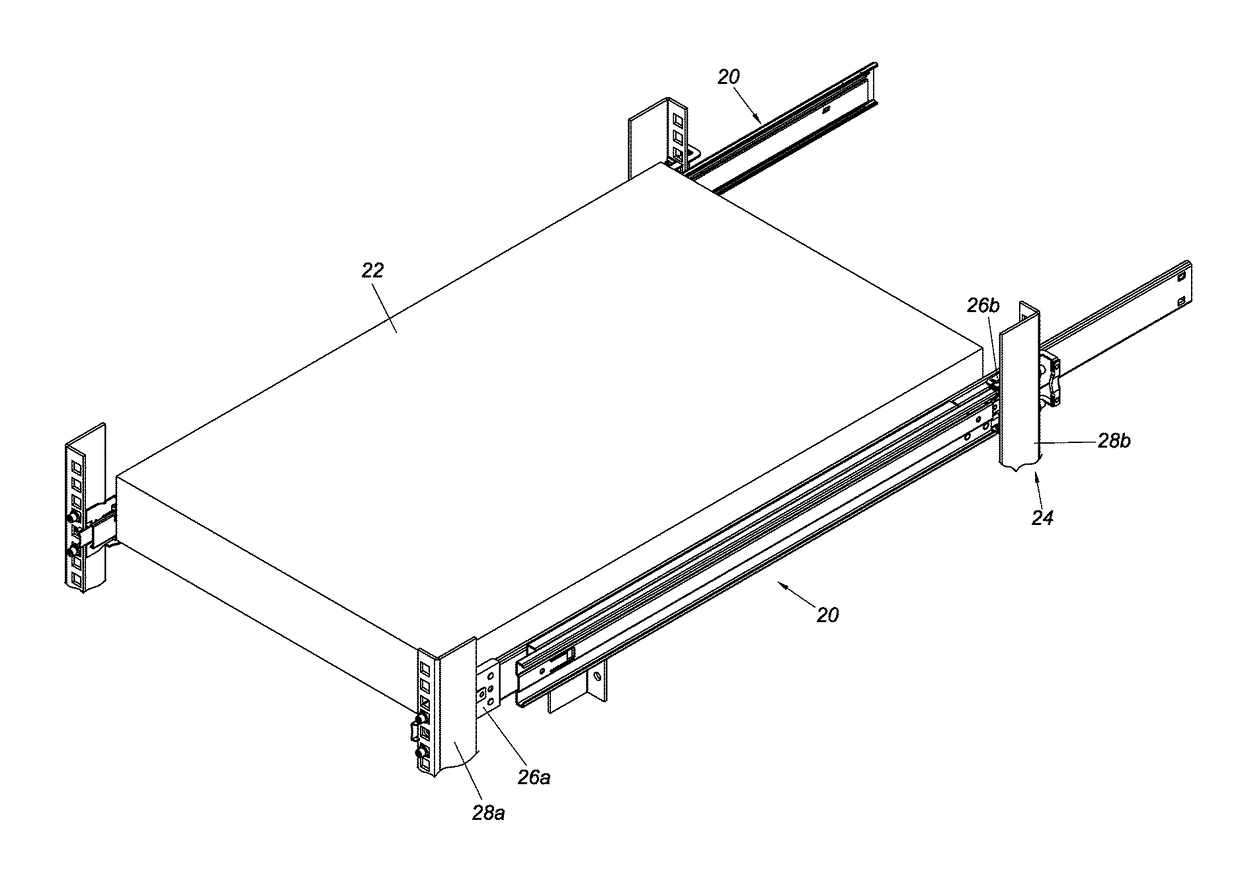
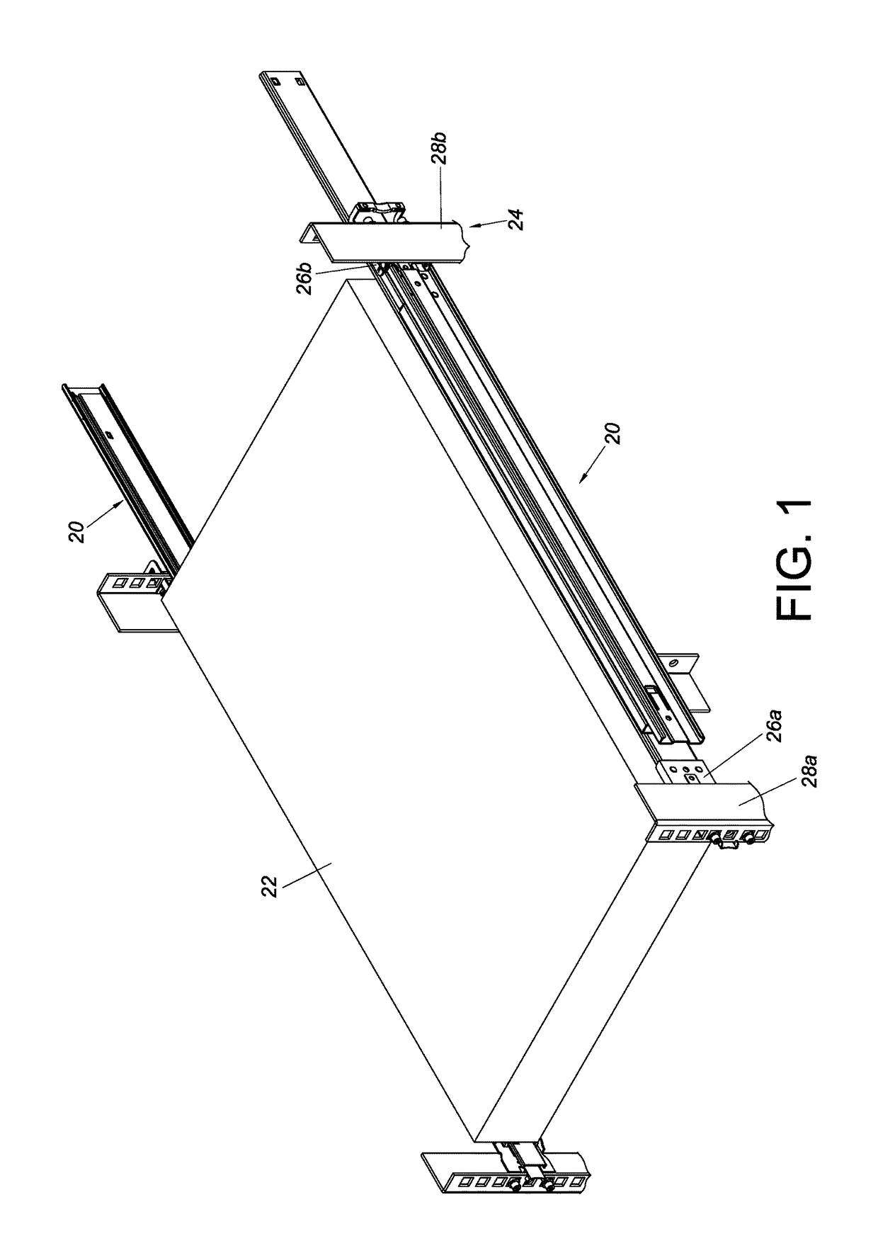
[0043]Referring to FIG. 1, the pair of slide rail assemblies 20 in an embodiment of the present invention are configured to mount an object 22 to a rack 24. More specifically, each slide rail assembly 20 can be mounted to a first post 28a and a second post 28b of the rack 24 via a first bracket 26a and a second bracket 26b respectively. The foregoing arrangement is well known in the art and therefore is not dealt with in more detail herein for the sake of simplicity.

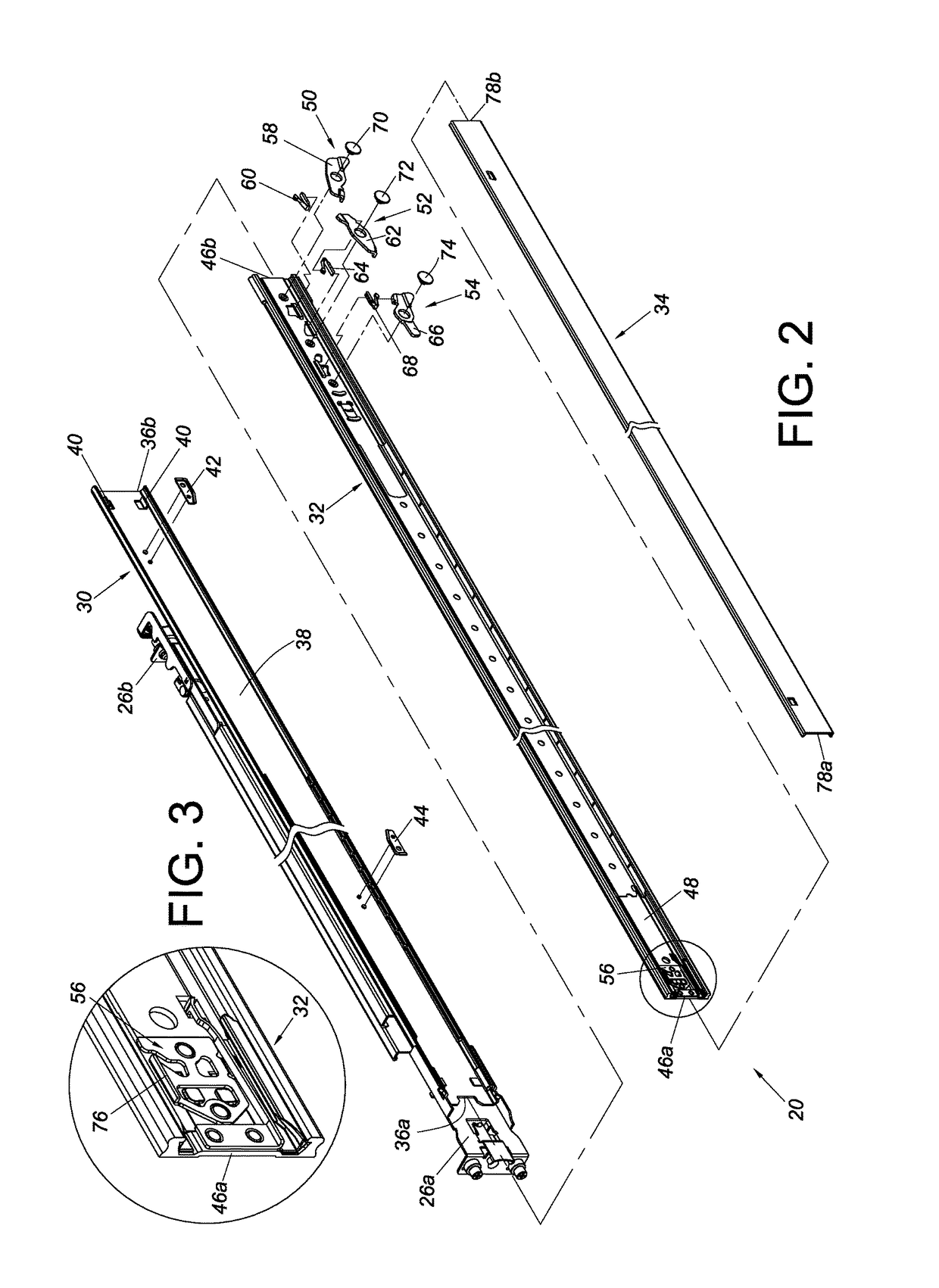
[0044]As shown in FIG. 2, the slide rail assembly 20 includes a first rail 30, a second rail 32, and a third rail 34. The first rail 30, on which the first bracket 26a and the second bracket 26b are arranged, has a front end 36a, a rear end 36b, and a first channel 38 between the front end 36a and the rear end 36b. Preferably, the first rail 30 also has at least one contact portion 40, such as two projections, adjacent to the rear end 36b. In this embodiment, the slide rail assembly 20 further includes a first stopping m...


PUM


Abstract

A slide rail assembly includes first to third rails and an engaging mechanism movably mounted on the second rail. The second rail is displaceable with respect to the first rail, and the third rail is displaceable with respect to the second rail. The three rails define a length when the second rail is displaced from a first to a second position in a first direction and the third rail, to a third position in the same direction, extending out of the second rail. Once the second rail is displaced from the second to a fourth position in a second direction, the length is reduced, and the second rail is kept at the fourth position by the engaging mechanism.

Description

FIELD OF THE INVENTION[0001]The present invention relates to a slide rail assembly and more particularly to one whose extended length can be reduced to facilitate installation and removal of a rail of the slide rail assembly in a space-limited environment.BACKGROUND OF THE INVENTION[0002]A slide rail assembly typically includes at least two rails which can be displaced with respect to each other to bring the slide rail assembly into an extended or retracted state. Take a three-part slide rail assembly with a first rail, a second rail, and a third rail for example. Usually, the slide rail assembly has a fully extended length when the second rail and the third rail have been displaced with respect to the first rail in a predetermined direction to their respective fully extended states, and the second rail can stay at a fully extended position with respect to the first rail once the slide rail assembly reaches the fully extended length.[0003]If it is desired, however, to keep the secon...

Claims


Application Information

Patent Timeline
IPC IPC(8): A47B88/08H05K7/18A47B88/16F16C29/12A47B88/04
CPCA47B88/08F16C29/123F16C2314/72A47B88/16H05K7/183A47B88/044A47B2210/0016H05K7/1489A47B2210/0081A47B88/443A47B88/493A47B88/49A47B88/43A47B88/57
Inventor CHEN, KEN-CHINGYANG, SHUN-HOLU, HSIAO-HANWANG, CHUN-CHIANG
Owner KING SLIDE WORKS CO LTD
Why Eureka
Try Eureka