Vasculature closure devices and automatic deployment systems

a technology of valve closure and automatic deployment, which is applied in the field of implantable medical devices and treatment methods, can solve the problems of increasing the potential for clots at the puncture site to become dislodged, affecting the effect of patient safety, and affecting the safety of patients,

Inactive Publication Date: 2017-07-27
E PACING
View PDF4 Cites 5 Cited by
  • Summary
  • Abstract
  • Description
  • Claims
  • Application Information

AI Technical Summary

Benefits of technology

[0010]In some embodiments, the vasculature closure device delivery system also includes an implant holder configured to hold the vasculature closure device for delivery into the vessel, a restraining thread configured to maintain the vasculature closure device in a collapsed configuration during delivery into the vessel, and a release wire configured to release the vasculature closure device from the implant holder and the restraining thread, such that the vasculature closure device is allowed to expand from the collapsed configuration into an expanded configuration. A first end of the release wire may be connected to the handle, and a second end portion of the release wire may engage the implant holder and the restraining thread. In some embodiments, the release wire is configured to release the vasculature closure device from the implant holder and the restraining thread upon movement of the handle and the push rod from the pre-deployment configuration to the deployment configuration. In some embodiments, the release wire is configured to release the vasculature closure device from the implant holder and the restraining thread when a resistance force provided by the vasculature closure device positioned at the puncture site is greater than a spring force provided by the spring mechanism.
[0011]In some embodiments, the vasculature closure device delivery system also includes a resistance element configured to resist removal of the vasculature closure device prior to expansion of the vasculature closure device. The release wire may be configured to release the vasculature closure device from the implant holder and the restraining thread when a sum of a resistance force provided by the resistance element and a resistance force provided by the vasculature closure device positioned at the puncture site is greater than a spring force provided by the spring mechanism. The resistance element may include a wire extending over a distal portion of the vasculature closure device. In some embodiments, the vasculature closure device delivery system also includes a resistance element restraining thread configured to maintain the resistance element in a constrained configuration prior to release of the vasculature closure device, and allow the resistance element to move to an unconstrained configuration upon release of the vasculature closure device. The resistance element may be configured to provide a first resistance force when in the constrained configuration and a second resistance force when in the unconstrained configuration, wherein the first resistance force is greater than the second resistance force. The resistance element may be configured to provide a resistance force that varies during delivery of the vasculature closure device.
[0012]According to another aspect, a vasculature closure system for closing a puncture site existing in a wall of a vessel is provided. In one or more embodiments, the vasculature closure system includes a vasculature closure device and a vasculature closure device delivery system. The vasculature closure device may include an expandable support frame deployable within the vessel, and a sealing membrane at least partially supported by the support frame, wherein the vasculature closure device is configured to expand from a collapsed configuration into an expanded configuration to intraluminally position the sealing membrane against the puncture site.
[0013]According to a further aspect, a method for closing a puncture site existing in a wall of a vessel is provided. In one or more embodiments, the method includes deploying a vasculature closure device intraluminally within the vessel via a vasculature closure device delivery system, and positioning a sealing membrane of the vasculature closure device against the puncture site.
[0014]According to still another aspect, a vasculature closure device delivery system for intraluminally positioning a vasculature closure device against a puncture site existing in a wall of a vessel is provided. In one or more embodiments, the vasculature closure device delivery system includes a loading tube configured to receive the vasculature closure device therein, a push rod configured to extend through the loading tube and to push the vasculature closure device out of the loading tube and into a lumen of the vessel, a handle configured to receive at least a portion of the push rod therein, and a spring mechanism comprising a first end connected to the push rod and a second end connected to the handle.

Problems solved by technology

This is quite difficult, not only because of the high blood pressure in the artery, but also because there are many layers of tissue that must be penetrated to reach the femoral artery.
This method, however, can take half an hour or more, and requires the patient to remain immobilized for at least that period of time and be subsequently kept in the hospital for observation.
In addition, this procedure increases the potential for clots at the puncture site to become dislodged.
Sutures, collagen plugs, adhesives, gels, and foams may have procedure variability, may require time to close the vessel, may have negative cost factors, may necessitate a possibly complicated deployment process, and may necessitate a separate deployment device.

Method used


Image

  • Vasculature closure devices and automatic deployment systems
  • Vasculature closure devices and automatic deployment systems
  • Vasculature closure devices and automatic deployment systems

Examples


Embodiment Construction

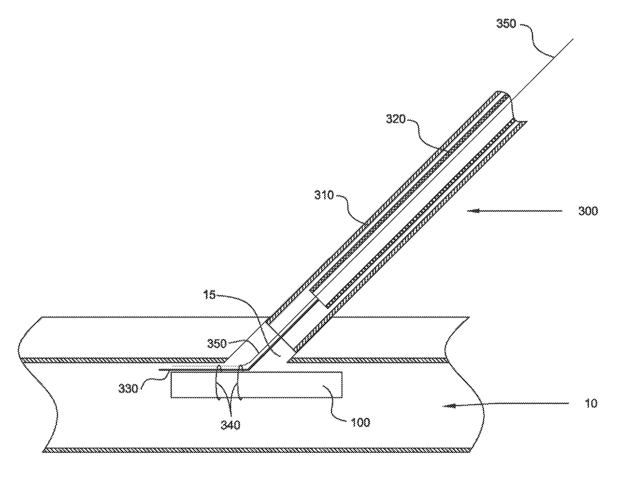
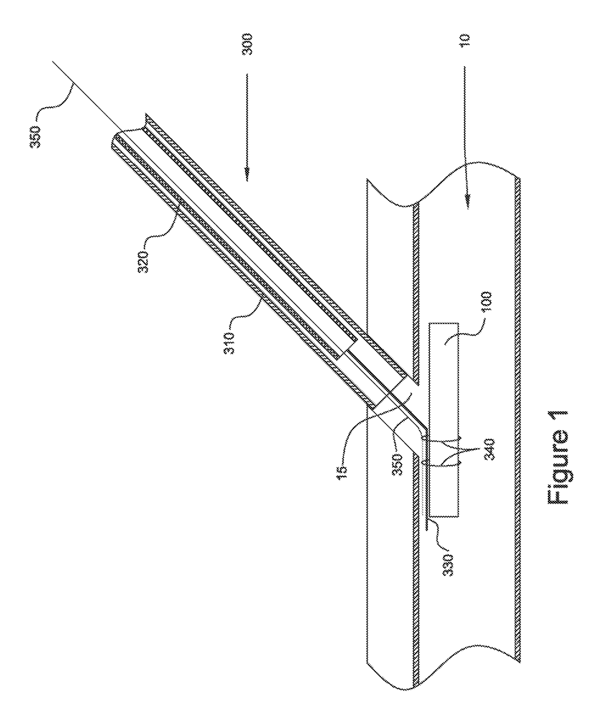
[0022]Vasculature closure devices (VCDs) and systems and methods for their use are provided to address some or all of the above-described needs. In particular, VCDs, VCD delivery systems, and VCD delivery methods that quickly and effectively close openings in vessel walls have been developed. Such VCDs, systems, and methods advantageously may avoid, or at least substantially reduce, the time and expense of applying manual pressure to an opening, simplify the steps required to close the opening, avoid widening of the opening, and more effectively retain the VCD in the vessel.

[0023]The VCDs, systems, and methods provided herein generally may be configured in a manner similar to the VCDs, systems, and methods provided in International Patent Application Publication No. WO 2011 / 046932 to Penner et al. and International Patent Application Publication No. WO 2013 / 188351 to Penner et al. (which are referred to herein as “the prior publications”), as will be appreciated upon review of the f...


PUM


Abstract

Vasculature closure device delivery systems and methods are provided. In one or more embodiments, a vasculature closure device delivery system for intraluminally positioning a vasculature closure device against a puncture site existing in a wall of a vessel includes a loading tube configured to receive the vasculature closure device therein, a push rod configured to extend through the loading tube and to push the vasculature closure device out of the loading tube and into a lumen of the vessel, and an automatic deployment mechanism configured to detect when the vasculature closure device is positioned at the puncture site and to automatically deploy the vasculature closure device thereabout.

Description

CROSS-REFERENCE TO RELATED APPLICATIONS[0001]This application claims the benefit of U.S. Provisional Application No. 62 / 029,008, filed on Jul. 25, 2014, which is incorporated herein by reference in its entirety.BACKGROUND[0002]This disclosure relates generally to the field of implantable medical devices and treatment methods, and more particularly to vasculature devices, systems, and methods for closing openings in vessel walls.[0003]During certain types of vascular surgery, catheters are inserted through an incision in the skin and underlying tissue to access an artery, such as the femoral artery, as one example. After the surgical procedure is completed and the catheter is removed from the patient, the access hole must be closed. This is quite difficult, not only because of the high blood pressure in the artery, but also because there are many layers of tissue that must be penetrated to reach the femoral artery.[0004]Physicians currently use a number of methods to close the artery...

Claims


Application Information

Patent Timeline
Patent Type & Authority Applications(United States)
IPC IPC(8): A61B17/00
CPCA61B17/0057A61B2017/00597A61B2090/0811A61B2017/00623A61B2017/0061A61B2017/00659
Inventor PENNER, ABRAHAMBEN-YOSEF, ALONWOLINSKY, LONE
Owner E PACING
Why Eureka
Try Eureka