Headend device of distributed antenna system and signal processing method thereof

a distributed antenna and headend device technology, applied in data switching networks, power management, transmission monitoring, etc., can solve the problems of limited transmission resources, power level of signals, restricted output from base stations, etc., and achieve the effect of evenly dispersing limited transmission resources

Active Publication Date: 2017-07-27
SOLID
View PDF3 Cites 2 Cited by
  • Summary
  • Abstract
  • Description
  • Claims
  • Application Information

AI Technical Summary

Benefits of technology

[0021]According to the headend device of the distributed antenna system and the signal processing method thereof according to the inventive concept, it can evenly distribute the limited transmission resources effectively for each of the base station signals by controlling the power of the base station signals according to the characteristic of the base station signals without the intervention of an administrator and it can aim at the convenience of the administrator.

Problems solved by technology

However, an output from a base station is restricted, and thus, a shadow area may exist due to the location of a base station or the topography of an area.
However, since there is a limit in increasing the power of a signal to improve the signal-to-noise ratio to increase the power of the signal, the power level of the signal, that is, the transmission resource is limited.
For that reason, in the case where various base station signals are combined to be transmitted as an optical signal, there is a problem that the distributed antenna system for providing a multi-band service should distribute appropriately the transmission resource for each of the base station signals so that the base station signals each are transmitted with an optimized power.
However, according to the conventional art, since the technician in the field often performs the repeated optimization of the transmission resource distribution of the distributed antenna system according to his ability, there is a problem that a lot of manpower and time is required.

Method used


Image

  • Headend device of distributed antenna system and signal processing method thereof
  • Headend device of distributed antenna system and signal processing method thereof
  • Headend device of distributed antenna system and signal processing method thereof

Examples


Embodiment Construction

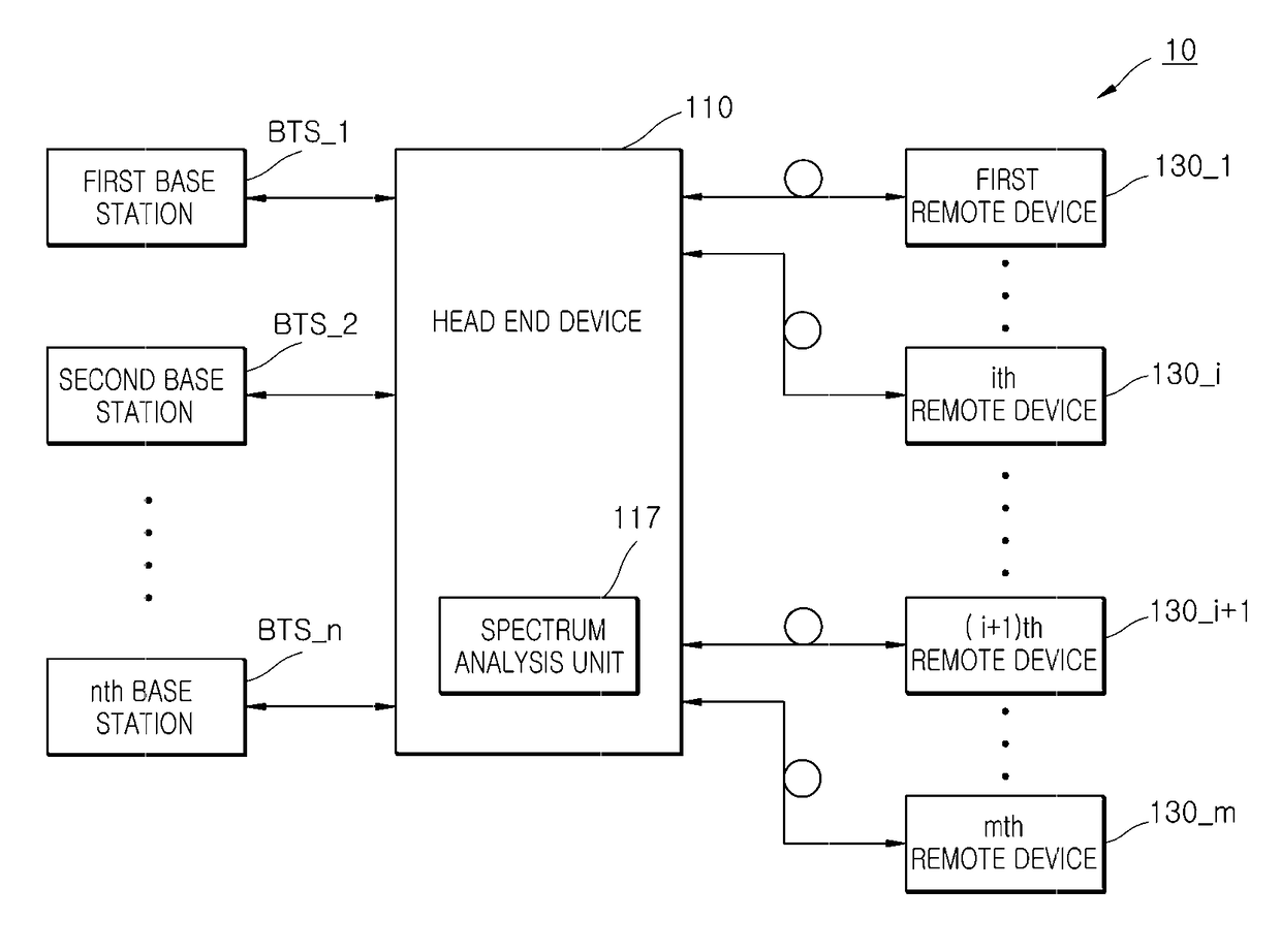
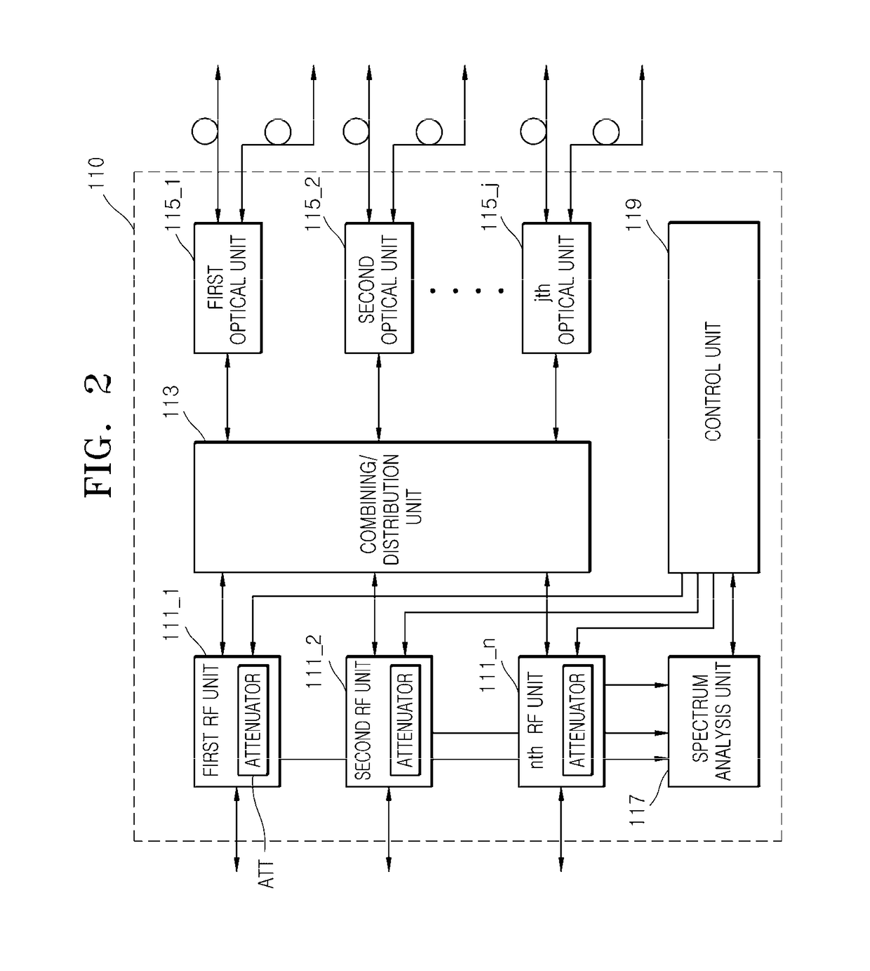
[0028]The inventive concept may be made with various changes and embodied in different forms, but, specific embodiments of the inventive concept will be described below in detail with reference to the accompanying drawing. However, this is not intended to limit the inventive concept to certain embodiments, but it should be understood as including all modifications, equivalents and substitutes included in the spirit and scope of the invention.

[0029]In the following descriptions of the inventive concept, if detailed descriptions of well-known technology that is determined to unnecessarily obscure the subject matter of the inventive concept, the detailed descriptions thereof will be omitted. Further, the numbers (e.g., the first, second, etc.) used in the course of being described in the specification are used just to distinguish one component from the other components.

[0030]Further, in this specification, when referred to as one component “is connected to” or “is accessed to” the othe...


PUM


Abstract

A headend device includes a spectrum analysis unit configured to analyze a frequency spectrum of a plurality of base station signals to detect characteristic information of the plurality of the base station signals, a control unit configured to generate a control signal to control a power of the plurality of the base station signals on the basis of the characteristic information detected, and a plurality of RF units configured to receive at least one of the plurality of the base station signals and adjust the power of the base station signals received according to the control signal and output the power-adjusted base station signals.

Description

TECHNICAL FIELD[0001]The inventive concept relates to a headend device of a distributed antenna system and a signal processing method thereof, and more particularly, to a headend device of a distributed antenna system which is capable of efficiently managing a limited transmission resource of a distributed antenna system, and a signal processing method thereof.BACKGROUND ART[0002]In general, with development of mobile communication, use patterns of and demands for a communication device of users have been diversified. Users wish to perform communication without time and space restriction. However, an output from a base station is restricted, and thus, a shadow area may exist due to the location of a base station or the topography of an area. In order to eliminate the shadow area, a distributed antenna system is used.[0003]The distributed antenna system includes a headend device coupled to the base station and a remote device coupled to the headend device through an optical cable. Th...

Claims


Application Information

Patent Timeline
Patent Type & Authority Applications(United States)
IPC IPC(8): H04W52/22H04B10/2575H04W52/24H04L12/26H04B17/327
CPCH04W52/228H04L43/18H04B17/327H04B7/2609H04B10/25753H04B7/04H04W52/245H04B7/15542
Inventor YEO, YEONG SHINNA, BONG CHEOL
Owner SOLID
Why Eureka
Try Eureka