Electronic smoking device and capsule

Active Publication Date: 2017-08-03
FONTEM HLDG 1
View PDF10 Cites 103 Cited by
  • Summary
  • Abstract
  • Description
  • Claims
  • Application Information

AI Technical Summary

Benefits of technology

[0015]Generally, it is possible to keep the costs for the e

Problems solved by technology

However, the amount of liquid remaining in a capsule cannot easily be detected by the electronic smoking device, and the capsule

Method used


Image

  • Electronic smoking device and capsule
  • Electronic smoking device and capsule
  • Electronic smoking device and capsule

Examples


Example

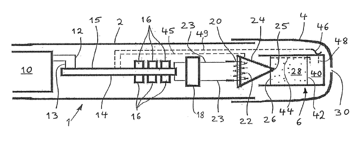
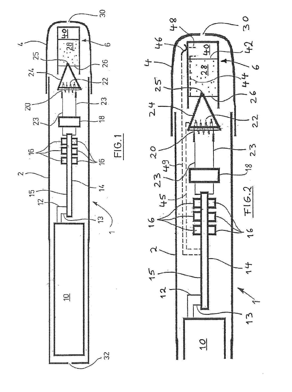
[0026]FIG. 1 illustrates an embodiment of a system comprising an electronic smoking device 1 and a capsule in a schematic longitudinal section.

[0027]The electronic smoking device 1 may include a cylinder-like housing 2 and a mouthpiece 4, which is designed as a detachable cap. Removing the mouthpiece 4 provides access to a replaceable capsule 6, which serves as a reservoir for a liquid and also contains an electronic controller.

[0028]The housing 2 holds a battery 10 which may be a re-chargeable battery, such as a lithium ion battery, with the battery 10 optionally including its own circuitry. The battery 10 is connected, via leads 12 and 13, to control electronics 14, which includes integrated circuits mounted on a printed circuit board 15. The printed circuit board 15 may also support light-emitting diodes (LEDs) 16 assembled behind respective windows provided in the housing 2 to indicate the current status of the electronic smoking device 1.

[0029]A puff detector 18 is connected to...


PUM


Abstract

A capsule (6) contains a liquid (28) to be supplied to an atomizer (20) and is mounted on or in an electronic smoking device (1). The capsule (6) has a controller (40) including a memory, which receives data from and transmits data to control electronics (14) of the electronic smoking device (1). A capacitor in the capsule (6) is charged by the electronic smoking device (1) and powers the controller (40) during intermediate intervals. Electrical contacts (26, 48) of the capsule are connected to electrical contacts (24, 46) of the electronic smoking device (1) to charge the capacitor and exchange data.

Description

[0001]The present application relates to a capsule for an electronic smoking device and a system comprising an electronic smoking device and a capsule, which can be mounted to the electronic smoking device.[0002]An electronic smoking device, such as an electronic cigarette, usually comprises a housing accommodating an electric power source (e.g., a battery), an atomizer including an electric heater adapted to atomize a liquid supplied from a reservoir or capsule into an aerosol, and control electronics which controls activation of the heater. A puff detector provided within the electronic smoking device is arranged to detect a user puffing on the device (e.g., by sensing an under-pressure or an air flow pattern through the device) and signals the puff to the control electronics. When a signal is detected the control electronics activates the atomizer, which creates an aerosol. The action of the atomizer is referred to as “atomizing” and the related product is called an “aerosol”, ir...

Claims


Application Information

Patent Timeline
IPC IPC(8): A24F47/00A24F40/10A24F40/42A24F40/53
CPCA24F47/008A61M15/06A61M2205/8206A24F40/42A24F40/10A24F40/53A61M15/0085A61M15/02A61M2016/0015A61M2205/3331A61M2205/52A61M2205/583A61M11/042A61M15/0035A61M15/008
Inventor ZITZKE, ROLAND
Owner FONTEM HLDG 1
Why Eureka
Try Eureka