Portable medical imaging system

a medical imaging system and portable technology, applied in the field of medical imaging systems, can solve the problems of inability to effectively position the system without moving the patient, and limited freedom of movement, and achieve the effect of facilitating the acceptance and use of mobile three-dimensional imaging systems

Active Publication Date: 2017-08-03
GLOBUS MEDICAL INC
View PDF25 Cites 153 Cited by
  • Summary
  • Abstract
  • Description
  • Claims
  • Application Information

AI Technical Summary

Problems solved by technology

While mobile solutions for ‘non-radiology department’ and patient-centric 3-D imaging do exist, they are often limited by their freedom of movement to effectively

Method used


Image

  • Portable medical imaging system
  • Portable medical imaging system
  • Portable medical imaging system

Examples


Embodiment Construction

[0015]For purposes of this application, the terms “code”, “software”, “program”, “application”, “software code”, “software module”, “module” and “software program” are used interchangeably to mean software instructions that are executable by a processor. A “user” can be a physician or other medical professional.

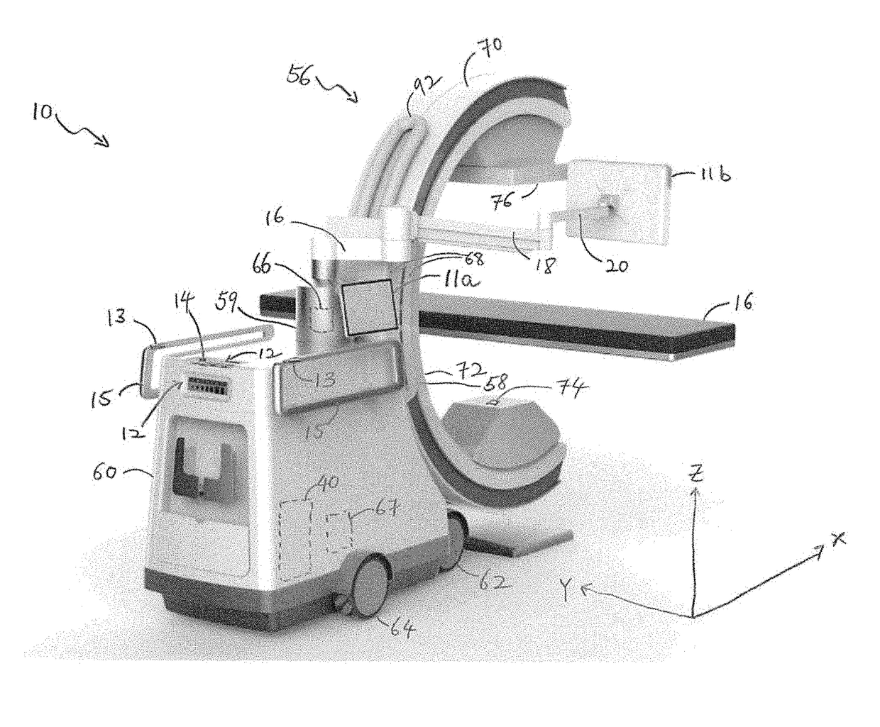
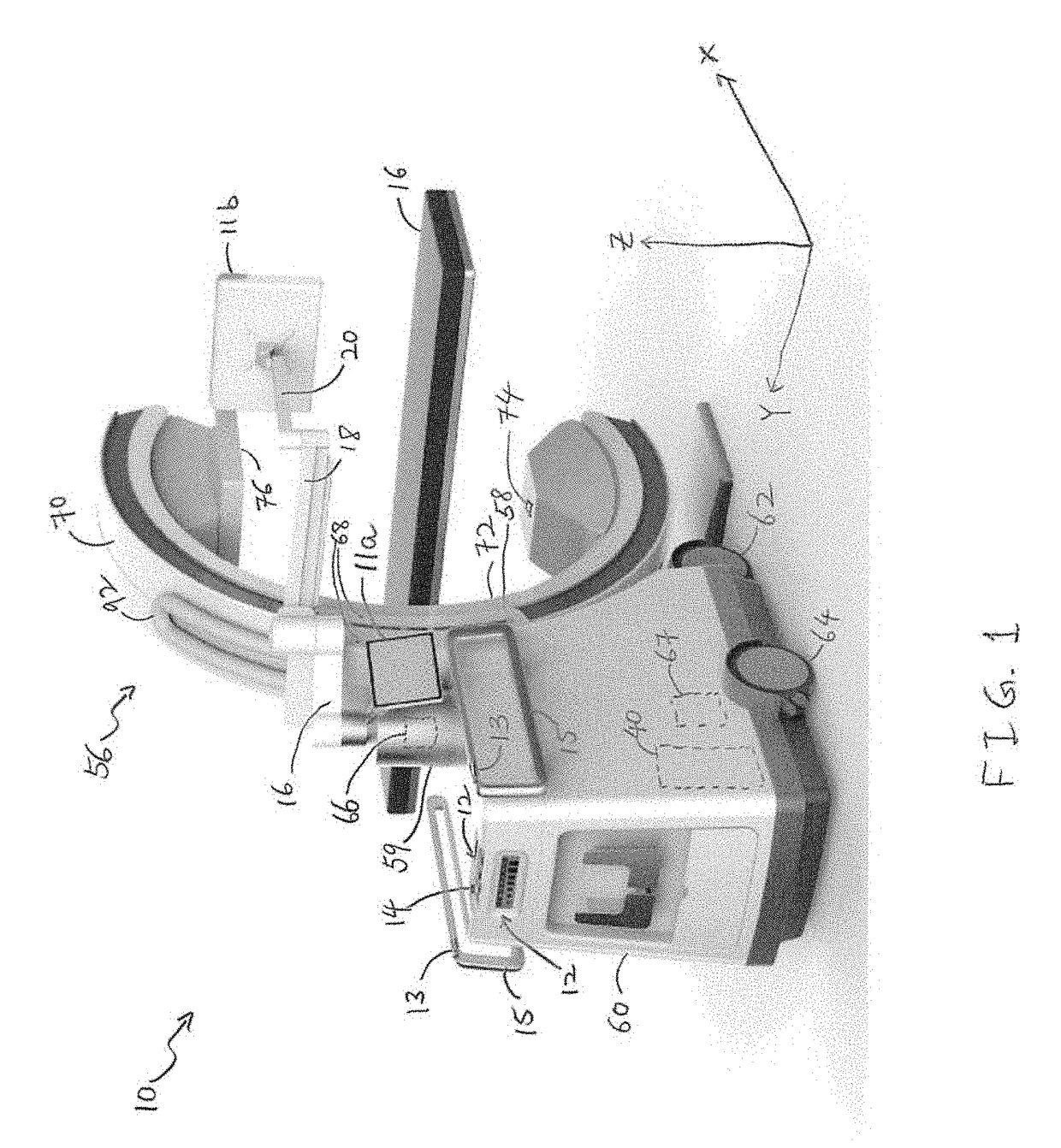
[0016]FIG. 1 is a schematic diagram showing an imaging system 10, such as a computerized tomographic (CT) x-ray scanner, in accordance with one embodiment of the invention. The imaging system 10 includes a movable station 60 and a gantry 56. The movable station includes a vertical shaft 59 and a gantry mount 58 which is rotatably attached to the vertical shaft. The movable station 60 includes two front omni-directional wheels 62 and two rear omni-directional wheels 64, which together provide movement of the movable station 60 in any direction in an X-Y plane. The omni-directional wheels 62,64 can be obtained, for example, from Active Robots Limited of Somerset, U.K. A pair of...


PUM


Abstract

A medical imaging system includes a movable station and a gantry. The movable station includes a gantry mount rotatably attached to the gantry. The gantry includes an outer C-arm slidably mounted to and operable to slide relative to the gantry mount, an inner C-arm slidably coupled to the outer C-arm and, an imaging signal transmitter and sensor attached to the C-arms. The two C-arms work together to provide a full 360 degree rotation of the imaging signal transmitter.

Description

TECHNICAL FIELD[0001]The present invention relates to medical imaging systems.BACKGROUND OF THE INVENTION[0002]Healthcare practices have shown the tremendous value of three-dimensional imaging such as computed tomography (CT) imaging, as a diagnostic tool in the Radiology Department. These imaging systems generally contain a fixed bore into which the patient enters from the head or foot. Other areas of care, including the operating room, intensive care departments and emergency departments, rely on two-dimensional imaging (fluoroscopy, ultrasound, 2-D mobile X-ray) as the primary means of diagnosis and therapeutic guidance.[0003]While mobile solutions for ‘non-radiology department’ and patient-centric 3-D imaging do exist, they are often limited by their freedom of movement to effectively position the system without moving the patient. Their limited freedom of movement has hindered the acceptance and use of mobile three-dimensional imaging systems.[0004]Therefore, there is a need fo...

Claims


Application Information

Patent Timeline
IPC IPC(8): A61B6/00A61B6/03
CPCA61B6/4405A61B6/54A61B6/4441A61B6/032A61B6/035A61B6/487A61B6/4085
Inventor JOHNSON, NORBERTSTEVENS, ROBERTSALEM, HISHAMCHENG, YUAN
Owner GLOBUS MEDICAL INC
Why Eureka
Try Eureka