Firearm grip with selector switch lock

a technology of selector switch and grip, which is applied in the direction of butts, weapons, weapon components, etc., can solve the problems of unauthorized access, one or more pieces of lock, and devices suffer from several drawbacks, so as to prevent excessive manual force and disable the engagement unit

Active Publication Date: 2017-08-03
GUN GUARDIAN
View PDF1 Cites 11 Cited by
  • Summary
  • Abstract
  • Description
  • Claims
  • Application Information

AI Technical Summary

Benefits of technology

[0009]Another embodiment of the present invention can include a user authentication unit in the form of an RFID interrogator and portable RFID chip. Upon detecting the presence of the RFID chip, the user authentication unit can position the engagement unit in the retracted position. Conversely, when the RFID chip is not within the proximity of the handgrip, the unit can position the engagement unit in the extended / SAFE position.
[0010]Yet another embodiment of the present invention can include a replacement selector switch having a torque limiter. The torque limiter can function to prevent an excessive manual force applied onto the selector switch from disabling the engagement unit.

Problems solved by technology

Although useful in their inception, these devices suffer from several drawbacks.
For example, because these locking mechanisms are externally mounted, it is not uncommon for one or more pieces of the lock to become lost when the same is not secured onto the weapon.
Additionally, it is not uncommon for users to secure the lock onto the weapon incorrectly, thereby causing a situation where unauthorized access can occur.
Finally, the time required to correctly secure and / or physically remove the external lock may be unacceptable in emergency situations where the user needs immediate access to the weapon.
Although the selector switch does work well to prevent an inadvertent discharge of the firearm, it does nothing to prevent an unauthorized user from firing the weapon by transitioning the switch from SAFE to FIRE.

Method used


Image

  • Firearm grip with selector switch lock
  • Firearm grip with selector switch lock
  • Firearm grip with selector switch lock

Examples


Embodiment Construction

[0027]While the specification concludes with claims defining the features of the invention that are regarded as novel, it is believed that the invention will be better understood from a consideration of the description in conjunction with the drawings. As required, detailed embodiments of the present invention are disclosed herein; however, it is to be understood that the disclosed embodiments are merely exemplary of the invention which can be embodied in various forms. Therefore, specific structural and functional details disclosed herein are not to be interpreted as limiting, but merely as a basis for the claims and as a representative basis for teaching one skilled in the art to variously employ the inventive arrangements in virtually any appropriately detailed structure. Further, the terms and phrases used herein are not intended to be limiting but rather to provide an understandable description of the invention.

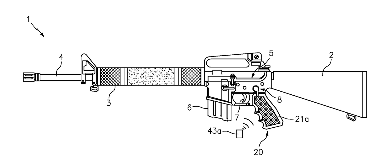
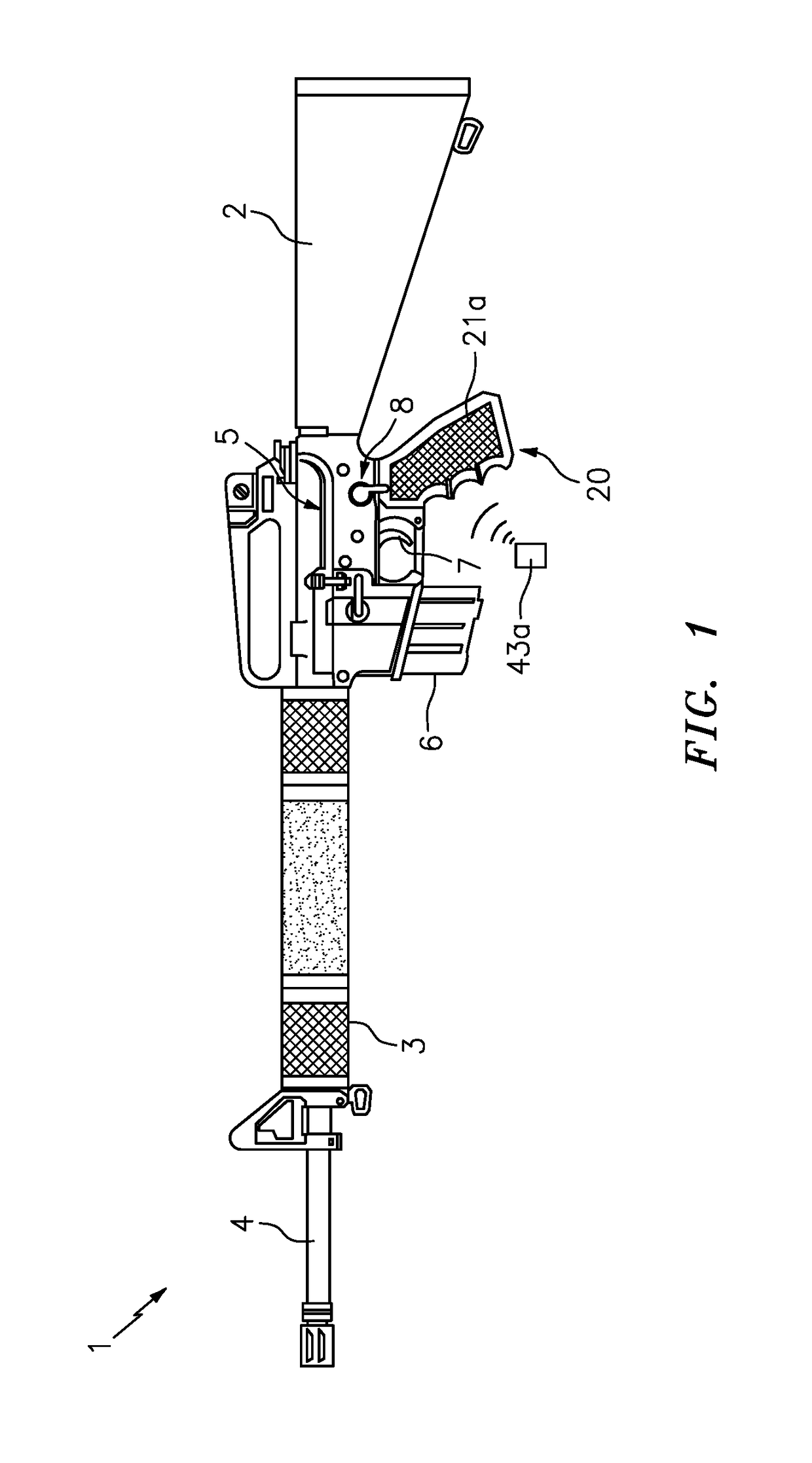
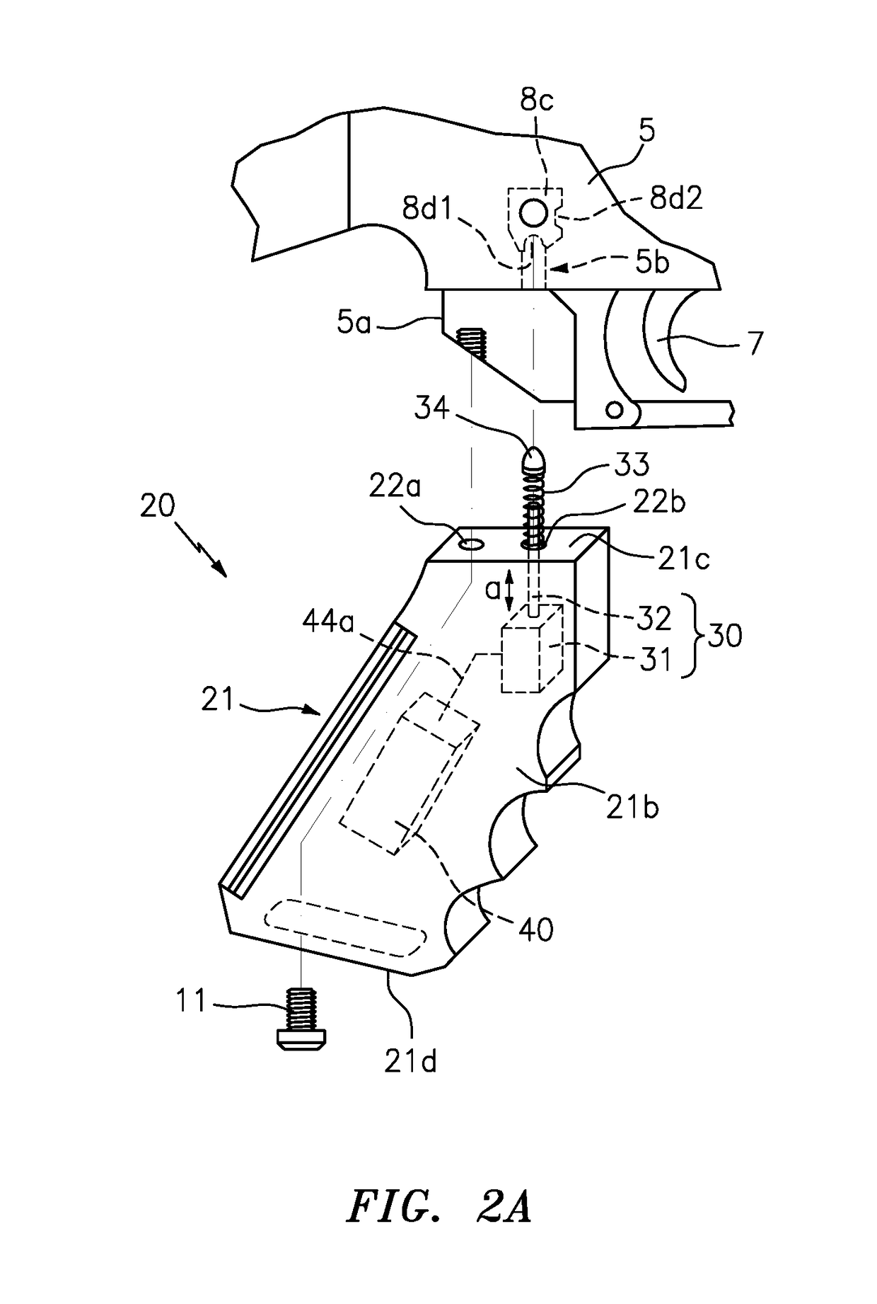
[0028]FIGS. 1-5C illustrate various embodiments of a firearm grip w...


PUM


Abstract

A firearm grip with selector switch lock includes a handgrip for engaging a firearm receiver having a selector switch. A switch engagement unit is positioned within the handgrip. The switch engagement unit including a motor, piston, spring and detent for selectively engaging the selector switch of the receiver to which the handgrip is located. An RFID interrogator is positioned within the handgrip and communicates with a portable RFID chip. Upon detecting the presence of the RFID chip, the switch engagement unit moves the piston to the retracted position for manual free operation of the selector switch. Upon detecting the RFID chip is not within the proximity of the handgrip, the switch engagement unit moves the piston to the extended/SAFE position. A replacement selector switch having a torque limiter is provided.

Description

CROSS-REFERENCE TO RELATED APPLICATIONS[0001]This application claims the benefit of U.S. Application Ser. No. 62 / 322,339 filed on Apr. 14, 2016, and is a continuation in part to copending application Ser. No. 15 / 261,279 having an original priority date of Oct. 16, 2015, the contents of each of which are incorporated herein by reference.TECHNICAL FIELD[0002]The present invention relates generally to firearm safety devices, and more particularly to a firearm grip having an internally located selector switch locking mechanism.BACKGROUND[0003]The statements in this section merely provide background information related to the present disclosure and may not constitute prior art.[0004]As any responsible firearm owner will attest, firearms should always remain locked when they are not in use, so as to prevent an accidental discharge of the same and / or to prevent access by an unauthorized individual. As such, there are many known types of commercially available firearm locking mechanisms suc...

Claims


Application Information

Patent Timeline
Patent Type & Authority Applications(United States)
IPC IPC(8): F41A17/06F41A17/20F41C23/10
CPCF41A17/06F41A17/20F41C23/10F41A17/063F41A17/066F41C23/16
Inventor MURPHY, II, WILLIAM LEWISHARVEY, ROBERT VAIL
Owner GUN GUARDIAN
Why Eureka
Try Eureka