
Control device, control method, and program

a control device and control method technology, applied in the field of control devices, control methods, programs, can solve the problems of increased difficulty in recognizing disadvantageous recognition of information displayed on the display unit, dangerous situations, etc., and achieve the effect of improving the visibility of the user wearable or portable display uni

Inactive Publication Date: 2017-08-03
SONY CORP
View PDF2 Cites 7 Cited by
  • Summary
  • Abstract
  • Description
  • Claims
  • Application Information

AI Technical Summary

Benefits of technology

The present disclosure relates to a control system for display information output on a user wearable or portable display unit. The system includes a controller that sets a threshold for afterimage recognition and adjusts the display output accordingly. If the user's eye movement velocity is slow, a high-pacing display is used, but if the velocity is high, a low-pacing display is used to improve visibility. This system helps improve the user's ability to see and interact with the display information.

Problems solved by technology

However, these portable or wearable display devices vibrate with the movement of the user, and thus it is difficult to recognize information displayed on a display unit disadvantageously.
The difficulty in recognizing such displayed information causes accidents due to distraction of attention to the surroundings and induction of eye fatigue, which may cause the occurrence of dangerous situations.
On the other hand, it is disadvantageously difficult to prevent vibration caused by the exercise such as walking or running, which lead to increased difficulty in recognizing information displayed on a display unit.
However, if the user performs an action such as walking or running, it is disadvantageously difficult for the user to recognize the display information.

Method used


Image

  • Control device, control method, and program
  • Control device, control method, and program
  • Control device, control method, and program

Examples


Embodiment Construction

[0064]The control device, control method, and program according to an embodiment of the present disclosure will be described in detail with reference to drawings. The description is made in the order of the following items.

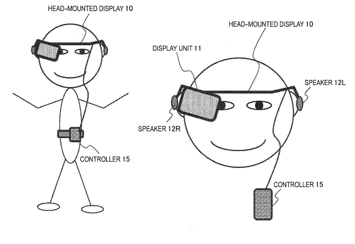
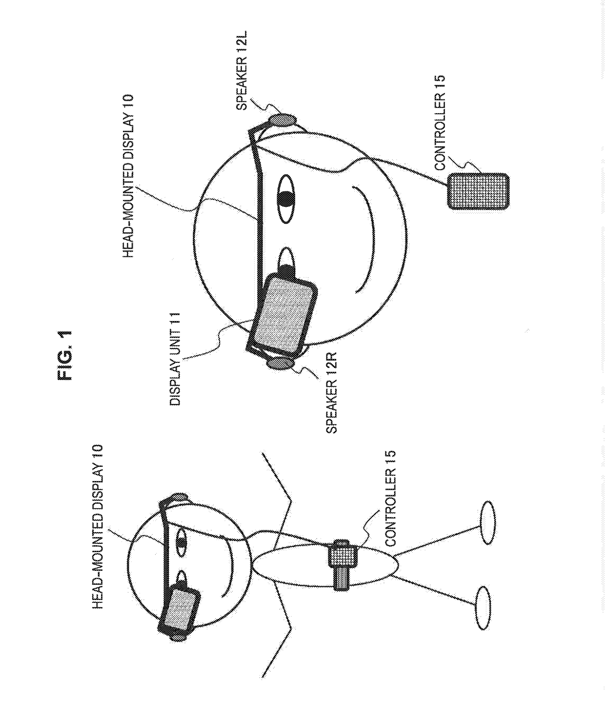
[0065]1. Exemplary Configuration of Head-mounted Display

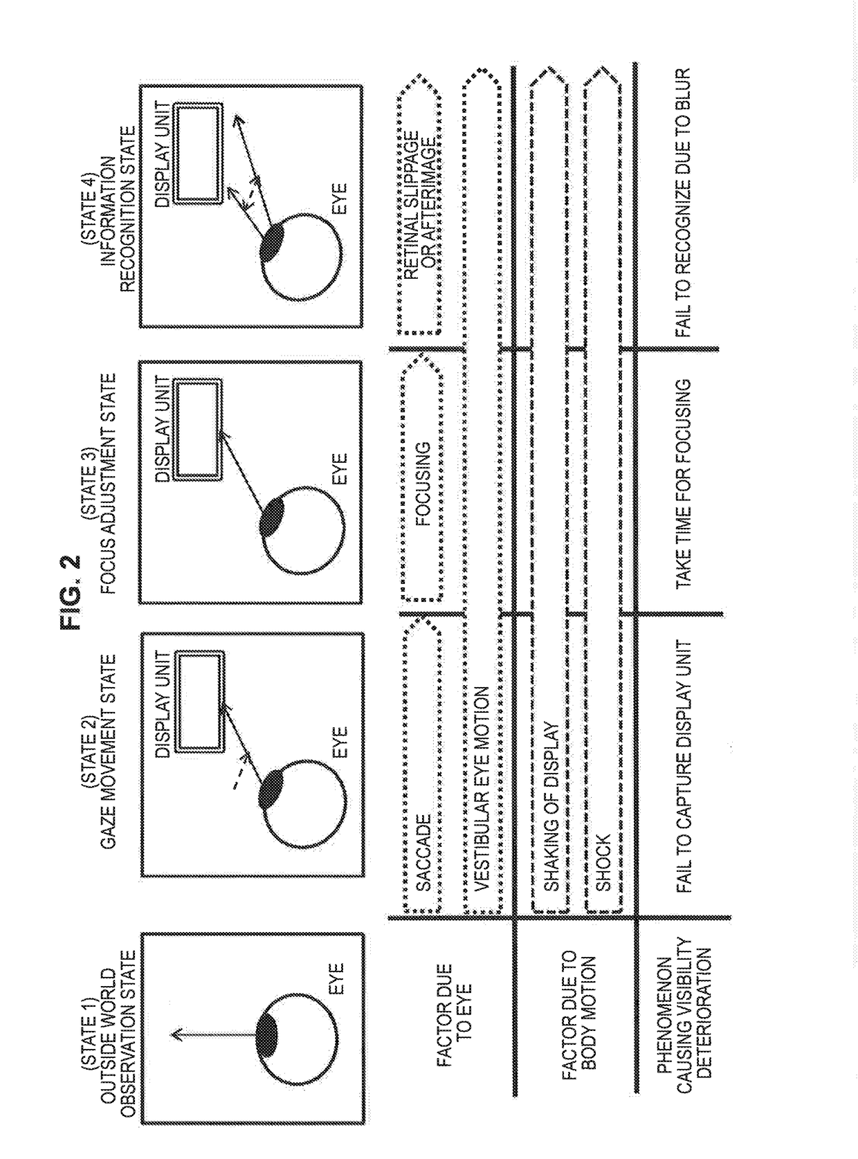
[0066]2. Factors and Examination of Visibility Deterioration of Display Information

[0067]3. Consideration on Prevention of Visibility Deterioration

[0068]4. Consideration on Visibility Deterioration due to Afterimage and Pursuit Eye Movement (Retinal slippage)

[0069]5. Prevention of Visibility Deterioration by Pulse Display

[0070]6. Principle of Visibility Improvement by Pulse Display

[0071]7. Configuration for Executing Control depending on Movement of User

[0072]8. Control of Display Timing in Pulse Display

[0073]9. Control of Luminance of Display Unit

[0074]10. Processing Procedure of Display Control[0075]10-1. Basic Procedure of Switching Control between Hold Display and Pulse Display[0076]10-2. Exercise Situati...


PUM


Abstract

Provided is a configuration for executing display information output control with improved visibility of a user wearable or portable display unit. A controller configured to execute display information output control on a user wearable or portable display unit is included. The controller sets a turning on (ON) period and a turning off (OFF) period and controls switching between afterimage consideration pulse display having the turning off period being set to be within an afterimage recognition period and normal pulse display having the turning off period being set to be longer than or equal to the afterimage recognition period, the turning on (ON) period being an output period of display information to the display unit, the turning off (OFF) period being a non-output period of display information to the display unit. The controller executes the switching control between the afterimage consideration pulse display and the normal pulse display depending on eye velocity of a user. The controller executes the afterimage consideration pulse display in a case where eye velocity of the user is less than a threshold and executes the normal pulse display in a case where the eye velocity is more than or equal to the threshold.

Description

TECHNICAL FIELD[0001]The present disclosure relates to control devices, control methods, and programs. In particular, the present disclosure relates to a control device, control method, and program for executing display control of a display device attached to the user's body or carried by the user such as head-mounted display that is a display worn by the user on the head.BACKGROUND ART[0002]Portable displays or wearable displays worn by the user on the head such as head-mounted display (HMD) have been recently widespread, and many users are using these portable or wearable display devices during moving or exercising. However, these portable or wearable display devices vibrate with the movement of the user, and thus it is difficult to recognize information displayed on a display unit disadvantageously. The difficulty in recognizing such displayed information causes accidents due to distraction of attention to the surroundings and induction of eye fatigue, which may cause the occurre...

Claims


Application Information

Patent Timeline
Patent Type & Authority Applications(United States)
IPC IPC(8): G02B27/01G09G5/00
CPCG02B2027/0187G02B2027/014G02B2027/0198G09G5/003G02B27/0179G02B27/017G02B27/0172G09G2230/00G09G3/20G09G3/34G09G5/00H04N5/64H04N5/66G09G3/001G09G3/2018G09G2320/0257G09G2320/0261G09G2340/0435G06F3/013G02B2027/0178G09G3/2014G02B27/0093G09G3/3233G02B2027/012G02B2027/0118G06F1/163
Inventor MAYAMA, ICHIROKIKUCHI, HIDENORITANAKA, KAYOKO
Owner SONY CORP
Learn More