High-frequency module

a high-frequency module and filter technology, applied in transmission, multiple-port network, electrical equipment, etc., can solve the problems of not being able to attenuate rf signals outside the pass band to a desired value, increasing the size of the high-frequency module that includes the filter b>500/b>, and increasing the size of the filter b>500/b>, so as to improve the isolation characteristics, improve the filter characteristics, and improve the effect of filtering

Active Publication Date: 2017-08-03
MURATA MFG CO LTD
View PDF1 Cites 41 Cited by
  • Summary
  • Abstract
  • Description
  • Claims
  • Application Information

AI Technical Summary

Benefits of technology

[0030]With this configuration, since a situation in which a high-frequency signal that is outside the frequency band of a transmission signal, which is the first high-frequency signal, and has substantially the same frequency band as a reception signal, which is the second high-frequency signal, flows around to the second filter side from the output-side signal path of the first filter and is output from the fourth terminal is suppressed, a high-frequency module is able to be provided that includes a first filter and a second filter having improved isolation characteristics.
[0031]According to various preferred embodiments of the present invention, a propagation path that improves filter characteristics is provided with a simple configuration by causing the inductor and the matching network to electromagnetic field couple with each other, and therefore the attenuation characteristics outside the frequency band of the first high-frequency signal are improved without increasing the size of the high-frequency module. In addition, unintended electromagnetic field coupling between the first filter and each inductor is significantly reduced or prevented by the shield electrode and therefore, unintended propagation of a high-frequency signal is significantly reduced or prevented. Therefore, attenuation characteristics outside the frequency band of the first high-frequency signal input to the first terminal are more effectively improved.

Problems solved by technology

However, it may not be possible to attenuate RF signals outside the pass band to a desired value using just the filter section 503.
Therefore, there is a problem in that the filter 500 is increased in size and a high-frequency module that includes the filter 500 is increased in size.

Method used


Image

  • High-frequency module
  • High-frequency module
  • High-frequency module

Examples


first preferred embodiment

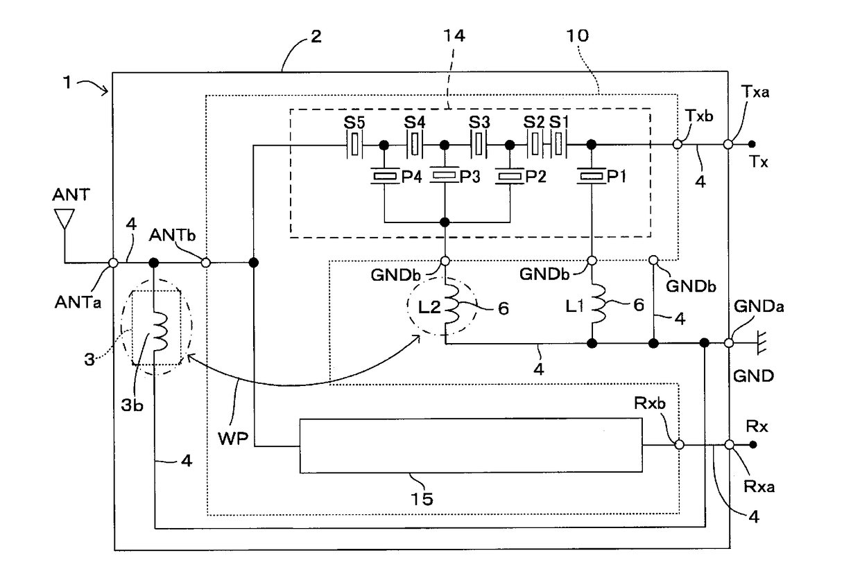
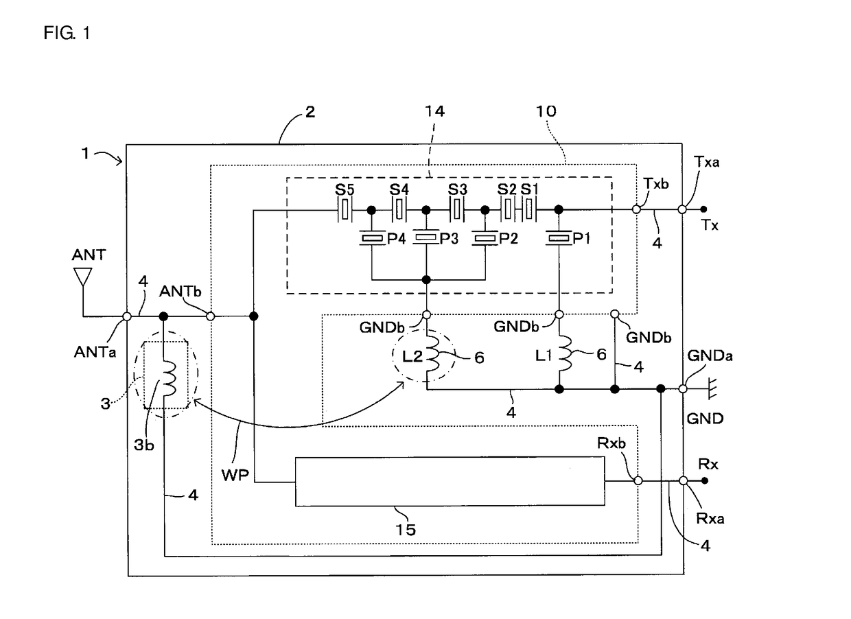
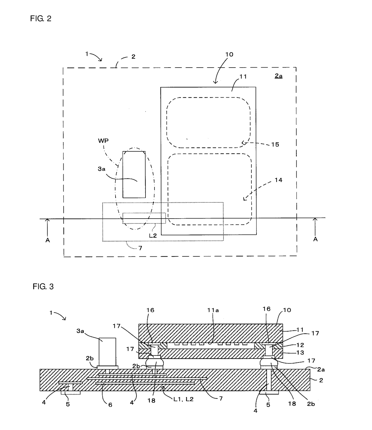
[0045]A first preferred embodiment of a high-frequency module of the present invention will be described while referring to FIGS. 1 to 5. In FIGS. 1 to 3, only important portions of the configuration related to the present invention are illustrated and illustration of other portions of the configuration is omitted in order to simplify the description. Furthermore, in each of the figures referred to in subsequent descriptions, only the important portions of the configuration are illustrated, as in FIGS. 1 to 3 and description thereof is omitted in the subsequent descriptions.

[0046]A high-frequency module 1 illustrated in FIGS. 1 to 3 is to be mounted on a mother substrate of a mobile communication terminal such as a cellular phone or a mobile information terminal, for example. In this preferred embodiment, the high-frequency module 1 includes a filter component 10 (duplexer), which is provided with a first filter 14 and a second filter 15, a module substrate 2, a matching network 3, ...

second preferred embodiment

[0078]Next, a second preferred embodiment of the present invention will be described while referring to FIG. 6.

[0079]This preferred embodiment differs from the first preferred embodiment described above in that a portion of the inductor L2 (wiring electrodes 6) close to the circuit component 3a is not superposed with the shield electrode 7 in plan view, as illustrated in FIG. 6. The rest of the configuration is the same as in the first preferred embodiment described above and therefore the same symbols are used and description thereof is omitted.

[0080]By adopting this configuration, unwanted coupling between the inductor L2 and the first and second filters 14 and 15 is significantly reduced or prevented while adjusting the amount of electromagnetic field coupling between the inductor L2 and the matching network 3 by adjusting the surface area of the part where the inductor L2 does not overlap the shield electrode 7 in plan view by adjusting the surface area of the shield electrode 7...

third preferred embodiment

[0081]Next, a third preferred embodiment of the present invention will be described while referring to FIG. 7.

[0082]This preferred embodiment differs from the first preferred embodiment described above in that the shield electrode 7 is located on the mounting surface 2a of the module substrate 2, as illustrated in FIG. 7. The rest of the configuration is the same as in the first preferred embodiment described above and therefore the same symbols are used and description thereof is omitted. With this configuration as well, the same effect as with the first preferred embodiment described above is attained.


PUM


Abstract

A high-frequency module includes a propagation path that has a simple structure and improves filter characteristics by causing an inductor and a matching network to electromagnetic field couple with each other such that attenuation characteristics outside of a frequency band of a transmission signal are improved without increasing the size of the high-frequency module. In addition, unintended electromagnetic field coupling between a first filter and the inductor is significantly reduced or prevented by a shield electrode. Therefore, unintended propagation of a high-frequency signal is significantly reduced or prevented. Therefore, the attenuation characteristics outside of the frequency band of transmission signal input to the transmission terminal are improved more effectively.

Description

CROSS REFERENCE TO RELATED APPLICATIONS[0001]This application claims the benefit of priority to Japanese Patent Application No. 2014-211590 filed on Oct. 16, 2014 and is a Continuation Application of PCT Application No. PCT / JP2015 / 078996 filed on Oct. 14, 2015. The entire contents of each application are hereby incorporated herein by reference.BACKGROUND OF THE INVENTION[0002]1. Field of the Invention[0003]The present invention relates to a high-frequency module that includes a module substrate on which a filter component is mounted.[0004]2. Description of the Related Art[0005]In the related art, high-frequency modules equipped with filters have been provided. For example, a filter 500 illustrated in FIG. 12 is mounted in a high-frequency module (for example, refer to Japanese Unexamined Patent Application Publication No. 2012-109818). The filter 500 includes a filter section 503, which is connected between a first terminal 501 and a second terminal 502, and a path 504 that is conne...

Claims


Application Information

Patent Timeline
Patent Type & Authority Applications(United States)
IPC IPC(8): H03H9/00H03H9/25H03H9/64
CPCH03H9/0009H03H9/25H03H9/64H03H7/38H03H9/1071H03H9/706H03H9/725H04B1/525H03H7/01
Inventor MIZOGUCHI, SHINYA
Owner MURATA MFG CO LTD
Why Eureka
Try Eureka