Fitting device for tire assembly and fitting method for tire assembly

Active Publication Date: 2017-08-10
HONDA MOTOR CO LTD
View PDF2 Cites 3 Cited by
  • Summary
  • Abstract
  • Description
  • Claims
  • Application Information

AI Technical Summary

Benefits of technology

[0029]Conventionally, striking has been applied to a pair of bead portions of a tire using an upper striking roller and a lower striking roller, individually and separately.
[0030]Concerning this point, with the invention according to claim 1, the lower striking roller is eliminated by replacing the lower striking roller with the receiving roller. The lower striking roller according to the conventional technique required a swing arm, a cam for swinging the swing arm, and an electric motor for rotating the cam. However, according to the present invention, the swing arm, the cam, and the motor for the lower striking roller are rendered unnecessary in their entirety.
[0031]As a result, according to the present invention, a fitting device for a tire assembly is provided, which is both simple in structure and in

Problems solved by technology

If such fitting is insufficient, gaps can be formed between the rim part and the bead portions.
However, in the fitting device according to Patent Document 1, it is nece

Method used


Image

  • Fitting device for tire assembly and fitting method for tire assembly
  • Fitting device for tire assembly and fitting method for tire assembly
  • Fitting device for tire assembly and fitting method for tire assembly

Examples


Example

[0045]An embodiment of the present invention will be described below with reference to the accompanying drawings.

Embodiment

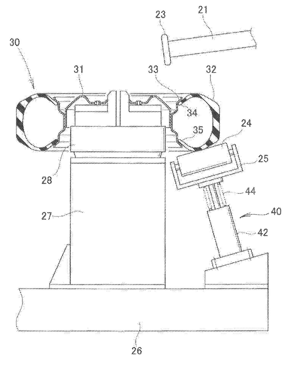
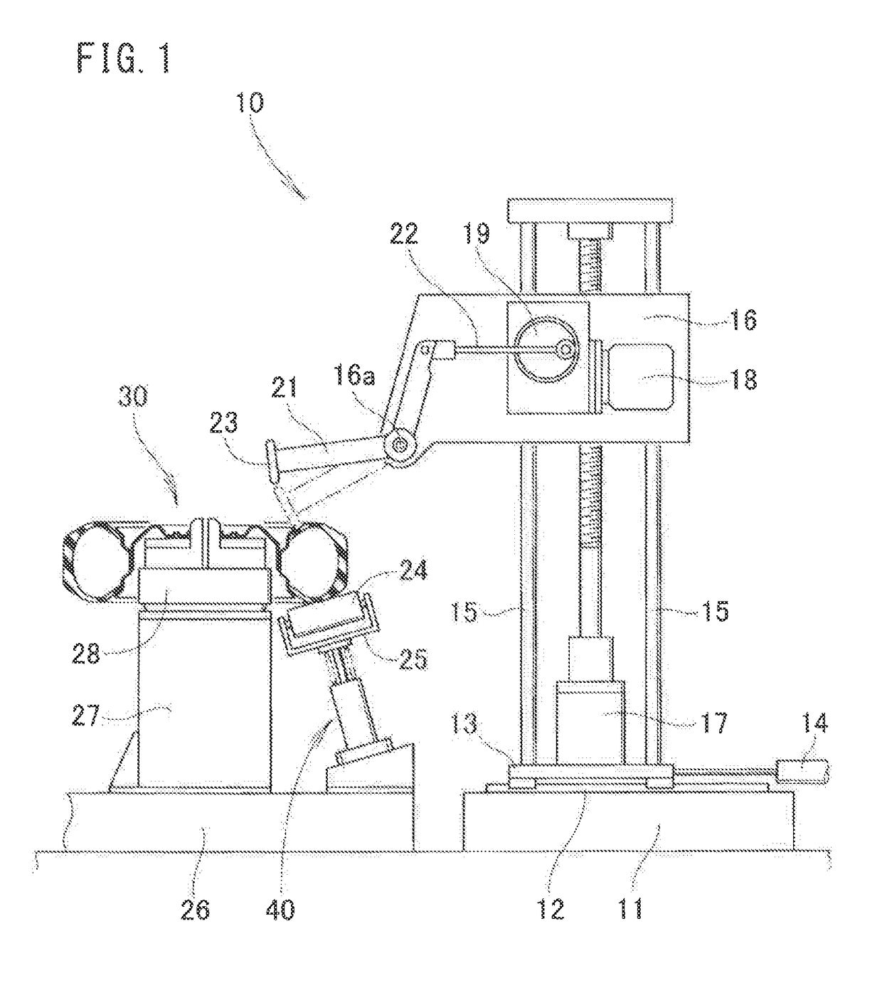
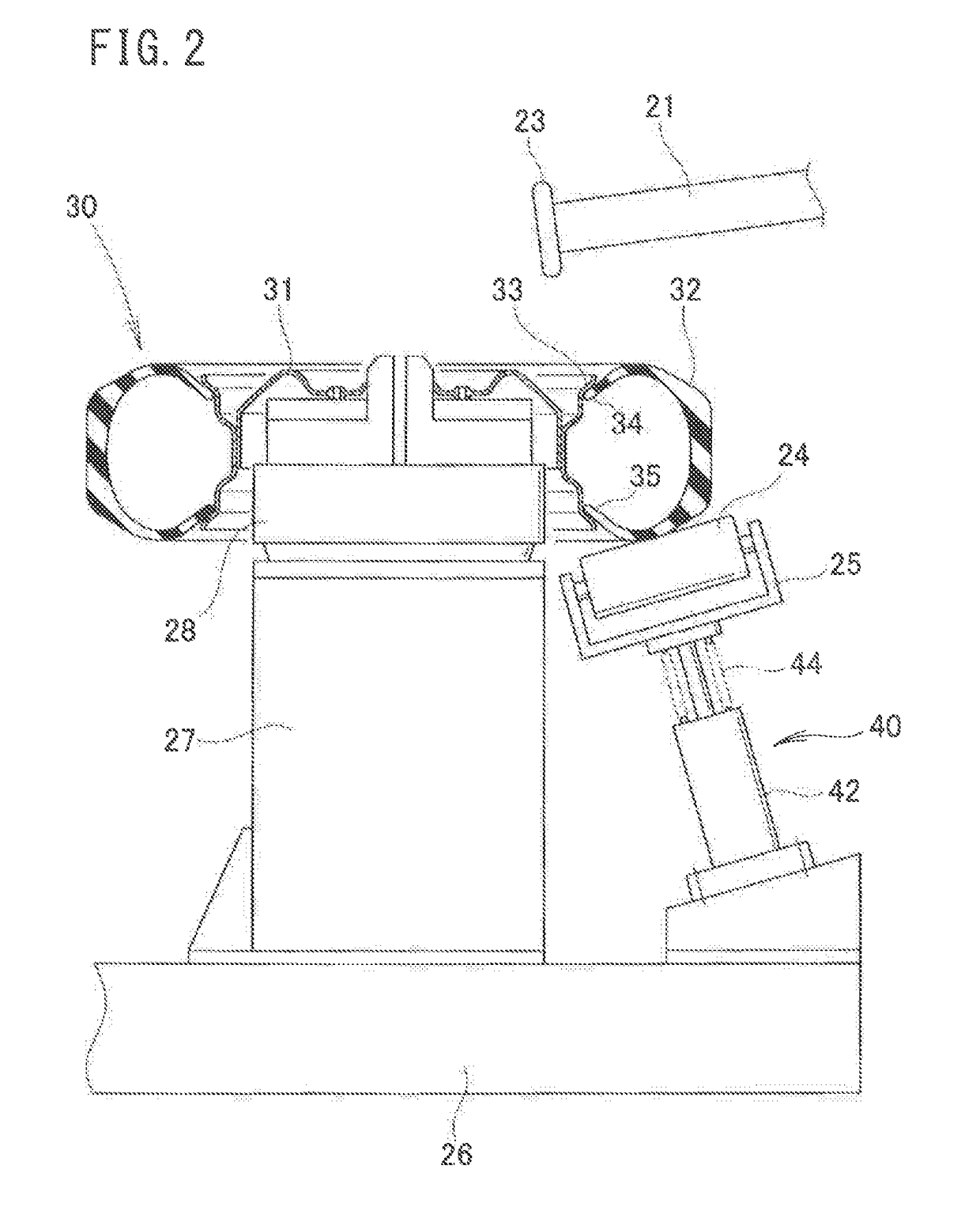
[0046]As shown in FIG. 1, a fitting device 10 is equipped with a pedestal 11, a rail 12 laid horizontally on an upper surface of the pedestal 11, a slider 13 which is mounted on the rail 12 for horizontal movement thereon, a moving cylinder 14 that moves the slider 13, two support posts 15, 15 erected on the slider 14, a lifting plate 16 that moves up and down while being guided by the support posts 15, 15, a jack mechanism 17 for raising and lowering the lifting plate 16, a cam rotating mechanism 18 attached to the lifting plate 16, a cam 19 that is rotated by the cam rotating mechanism 18, a V-shaped arm 21 which is swingably mounted on the lifting plate 16 by a pin 16a, a connecting rod 22 that connects a proximal portion of the arm 21 with the cam 19, a striking roller 23 disposed on a distal end of the arm 21, a receiving roller 24 disposed face-to-face wit...


PUM


Abstract

A tire fitting device includes: an arm for moving toward a tire; a striking roller for applying a striking force in the vicinity of a bead part, the striking roller being attached to the arm; a receiving roller for receiving the tire to which the striking force is applied; and an elastic member for elastically supporting the receiving roller.

Description

TECHNICAL FIELD[0001]The present invention relates to a fitting device for applying a striking force to a tire of a tire assembly as well as to a fitting method for such a tire assembly.BACKGROUND ART[0002]A tire assembly is composed of a wheel and a tire fitted onto the wheel. More specifically, bead portions of the tire are fitted onto a rim part of the wheel. If such fitting is insufficient, gaps can be formed between the rim part and the bead portions. Such gaps have an influence on traveling of the vehicle.[0003]When intervening air residing within the gaps is expelled, the bead portions can be brought into tight contact with the rim part, and if such tight contact is achieved, the gaps disappear.[0004]Conventionally, a technique of striking in the vicinity of the bead portions of the tire with a hammer in order to flush out air has been known (see, for example, Patent Document 1).[0005]The fitting device disclosed in Patent Document 1 is equipped with an upper hammer above the...

Claims


Application Information

Patent Timeline
IPC IPC(8): B60C25/14B60C25/12
CPCB60C25/12B60C25/14
Inventor ICHINOSE, HIDEMITSUJI, YOSHITERUNISHIYAMA, MASARU
Owner HONDA MOTOR CO LTD
Why Eureka
Try Eureka