Ear gear with earpieces interconnected through headband with two legs

Active Publication Date: 2017-08-10
ZOUND IND INT AB
View PDF1 Cites 6 Cited by
  • Summary
  • Abstract
  • Description
  • Claims
  • Application Information

AI Technical Summary

Benefits of technology

[0021]According to one aspect of the invention, the recess is provided with an enlarged space adjacent the position of the stop member on the leg. This is advantageous from a production and cost efficient view.
[0022]According to yet a further aspect of the invention one or more bridging elements are arranged to engage the legs of the headband along at least at one section between the end regions. This has the effect that it is possible to limit the headband twist rotation in order to avoid over-rotation of the legs of the headband.
[0023]According to one aspect of the invention the extended legs are formed by at least two wires, the wires are running essentially parallel between a respective headband end region. This has the effect that it is possible to provide the headband with excellent flexible properties.
[0024]According to a further aspect of the inve

Problems solved by technology

There is a challenge in designing a headset/headphone with good ergonomics.
The same problem regarding improper ergonomics as mentioned above exists with ear protection of the kind comprising two ear cups that are connected with a headband.
However, too high clamp force can be painful for the user.
Another way to get a good seal is to have a big and flexible ear-cushion, however the good foam materials tend to be rather expensive and it is often desired to keep the size of the ear gear down in order to look nice on the head.
A

Method used


Image

  • Ear gear with earpieces interconnected through headband with two legs
  • Ear gear with earpieces interconnected through headband with two legs
  • Ear gear with earpieces interconnected through headband with two legs

Examples


first embodiment

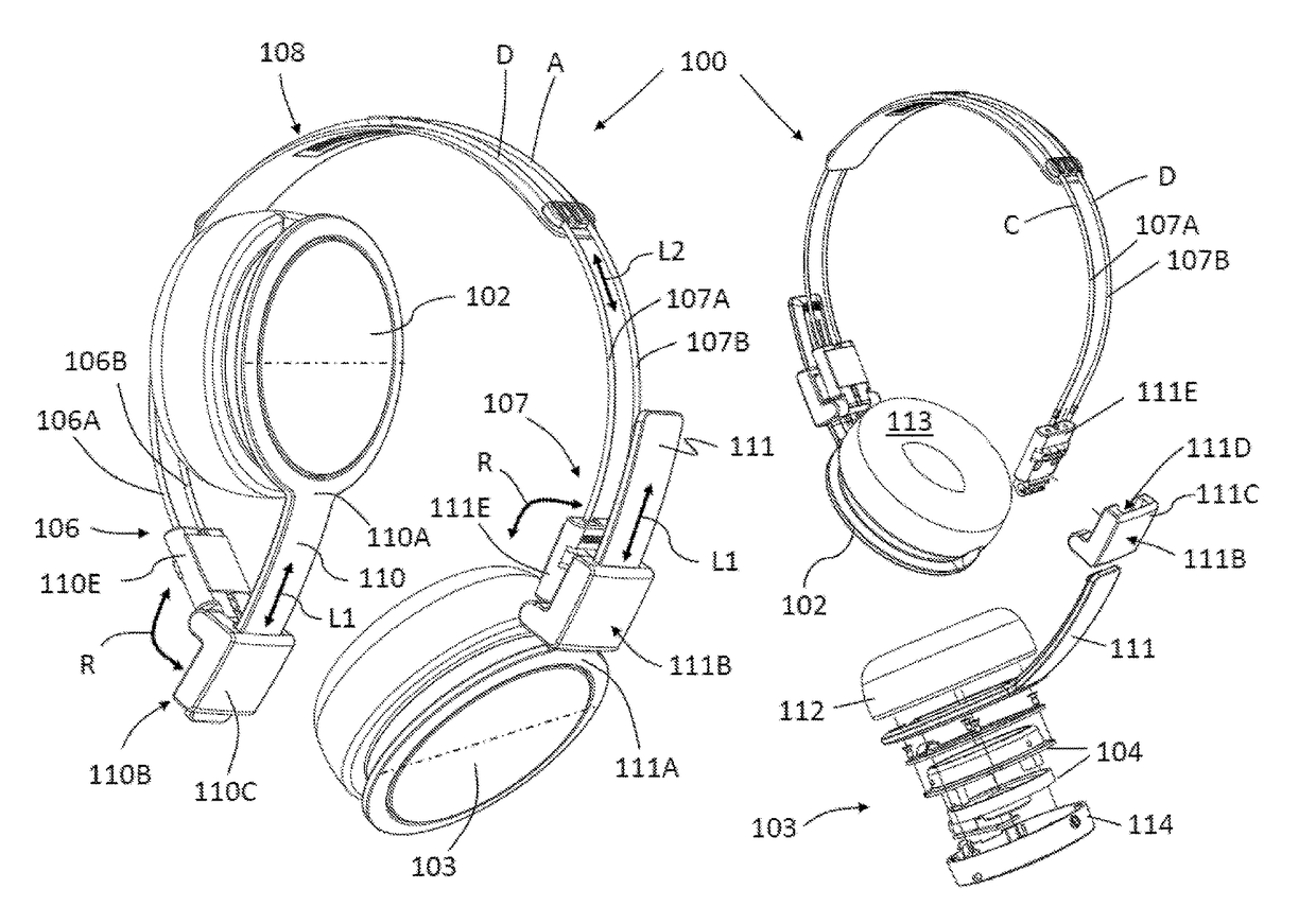
[0041]In FIG. 2 is shown an example of ear gear in this example a headphone assembly 100. The headphone assembly 100 having a pair of earpieces 102, 103 each with associated speaker units 104, being attached generally to a respective end region 106, 107 of an interconnecting headband 108. Each earpiece 102, 103 are adjustably associated with the headband 108, for adjustment of the position of the earpieces 102, 103 relative to the headband 108. Further, the end regions 106, 107 of the headband 108 are provided with at least two extending legs 106A, 106B and 107A, 107B, respectively. As shown in FIG. 2, the headphone assembly 100 may further comprise arm members 110, 111 that at one end 110A, 111A are attached or integrated in one piece with a respective earpiece 102, 103. Although not shown in FIG. 2, the arm members 110, 111 can be formed as wire loops. As shown in this example in FIG. 2, the headphone assembly 100 may further comprise earpiece hinges 110B, 111B, each being suppor...

second embodiment

[0046]FIG. 3 shows a perspective view of a headphone assembly 200 according to the present invention. The headphone assembly 200 having a pair of earpieces 203 (only one is shown in FIG. 3) each with associated speaker units, being attached generally to a respective end region 206, 207 of an interconnecting headband 208. Each earpiece 203 is adjustably associated with the headband 208, for adjustment of the position of the earpieces 203 relative to the headband 208. Further, the end regions 206, 207 of the headband 208 are provided with at least two extending legs 206A, 206 B and 207A, 207B, respectively. As shown in FIG. 3, the headphone assembly 200 may further comprise arm members 211 (only one is shown at earpiece 203) that at one end 211A is attached or integrated in one piece with a respective earpiece 203. Although not shown in FIG. 3, the arm members 211 can be formed as wire loops. As shown in this example in FIG. 3, the headphone assembly 200 does not comprise earpiece hin...

third embodiment

[0050]In FIGS. 4A, 4B and 4C the legs forming the headband of a headphone assembly of the kind shown in FIG. 2 above are shown, according to a According to the embodiment described and shown in FIGS. 4A, 4B and 4C, the same reference numbers as in the embodiment of FIG. 2 have been used for the similar features. Each end cap 110E, 111E have recesses in the form of elongated holes 116 (see also FIG. 5D described below) and where each of the legs are inserted in the holes 116. Suitably, the holes are blind holes 116 (also called dead end holes). As shown in FIG. 4A-B, each side of the legs 106A, 106B and 107A, 107B, respectively, of the headband are inserted in the end-caps 110E, 111E. As seen from FIGS. 4A, 4B and 4C, the side surface of the end cap may comprise windows 118 that have access from the side to the interior of the hole 116 and an inserted leg 106A, 106B and 107A, 107B, respectively, in the hole. The end regions 106, 107 of the legs are provided with stop members 120. It...


PUM


Abstract

The present invention relates to ear gear (100; 200), such as headphones, headset, ear protection or similar, having a pair of earpieces (102, 103; 203), being attached generally to a respective end region (106, 107; 206, 207) of an interconnecting headband (108; 208). Each earpiece is adjustably associated with the headband, for adjustment of the position of the earpieces relative to the headband. The ear gear further comprises at least two extending legs (106A, 106B, 107A, 107B; 206A, 206B, 207A, 207B) provided at the end region (106, 107; 206, 207) at the headband, and arm members (110, 11 1; 211) that at one end (110A, 111A; 211A) are attached to a respective earpiece. Further, the ear gear comprises an end cap (110E, 111E; 211E) provided at the respective headband end region (106, 107; 206, 207). At least one of the extended legs is rotatably arranged to each end cap (110E, 111E; 211E), such that the end cap can rotate relative to the at least one leg (106A, 106B, 107A, 107B; 206A, 206B, 207A, 207B).

Description

TECHNICAL FIELD[0001]The present invention relates to ear gear, such as headphones, headset, ear protection or similar.TECHNICAL BACKGROUND[0002]Ear gear such as headphones, headsets or ear protection are well known on the market. For instance, one kind of ear gear are typical headphones that comprises two (one left and one right) ear cups in which the sound generating speaker elements are located. Between the ear cups and the users head there are normally ear cushion rings or pads which seals the sound in and makes it comfortable towards the head or ear. The two ear cups are often connected with a headband. The headband or the area where the headband meets the ear cups does often comprise a size adjustment function. The headband also typically comprise a folding mechanism to make the headphone smaller when stored away. To handle different head sizes and individual dimensions, angels and shapes most headsets / headphones have a rotation axis (see FIG. 1A; reference character A). Some ...

Claims


Application Information

Patent Timeline
IPC IPC(8): H04R1/10
CPCH04R1/1066H04R1/1033H04R1/105H04R1/1008H04R5/0335H04M1/05
Inventor PETERSEN, ERIK
Owner ZOUND IND INT AB
Why Eureka
Try Eureka