
Valve monitoring

a valve and valve technology, applied in the direction of valve operating means/releasing devices, mechanical equipment, transportation and packaging, etc., can solve the problem of insufficient fluid flow to allow the sprinklers

Active Publication Date: 2017-08-17
AMTRON VALVE MONITORING DEVICE
View PDF5 Cites 10 Cited by
  • Summary
  • Abstract
  • Description
  • Claims
  • Application Information

AI Technical Summary

Benefits of technology

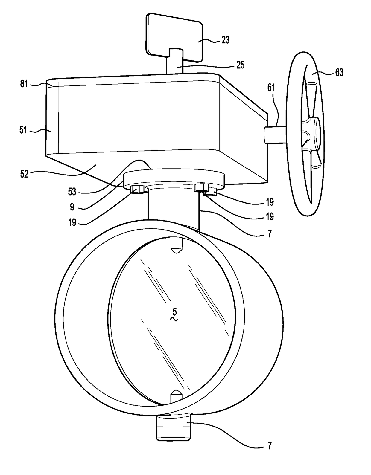
The invention is a valve gear box with a valve monitoring function. The gear box is designed to mount to a valve with a fluid passageway and a gate for opening and closing the passageway. The gear box has a mounting flange that can be connected to the valve, and a housing with a mounting for operative connection to the valve. A valve monitoring sensor is positioned in the mounting flange and can change state if the mounting flange is separated from the valve. The sensor can detect the separation of the mounting flange and trigger an alarm condition. The gear box also includes a gate position sensor that can change state when the gate is opened or closed. The gear box has a gear driven link with a shear separator that will still function even if there is an excess force applied to the operator handle. The gear box and its components are enclosed in a housing to prevent tampering. The housing has a lid sensor that can change state when the lid is opened or closed. The gear box is made of non-ferrous material and has a mounting that prevents external electrical junction boxes from being tampered with. The gear box also includes at least one magnetically operable protection sensor to prevent unauthorized access.

Problems solved by technology

Some gear boxes incorporate valve monitoring functions within these gear boxes to sense the open or closed condition of the valve, however, we have determined that there are deficiencies in existing valve monitoring techniques which allow the valve monitoring functions to be bypassed either for nefarious reasons or by tradespeople taking shortcuts during maintenance.
In this respect, it is critical particularly for sprinkler systems be fully operational as even a partial closure of the valve can result in insufficient fluid flow to allow the sprinklers to operate effectively if there is a fire.

Method used


Image

  • Valve monitoring
  • Valve monitoring
  • Valve monitoring

Examples


Embodiment Construction

[0041]It should be appreciated that the invention is applicable to valve monitoring in any environment where fluid is flowing in a fluid passageway and that the invention is not limited to use only in connection with fire alarm sprinkler installations.

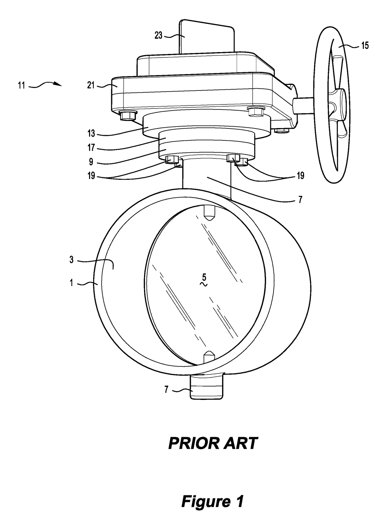
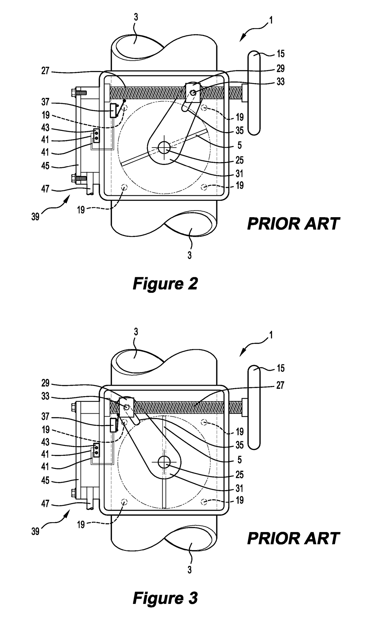
[0042]FIGS. 1 to 3 illustrate a prior art valve and valve gear box. It can be seen that a valve 1 has a fluid passageway 3, and gate 5 therein. The gate 5 is a butterfly gate that can move about a central upright axis from a closed position to an open position at 90 degree. The gate 5 has upper and lower bearing parts 7. The upper part 7 terminates with a valve mounting flange 9. A manually operated gear box 11 for swinging the gate 5 is provided in a housing 13. The gear box 11 contains a gear driven link for moving the gate 5 between open and closed conditions relative to the fluid passageway 3 in response to operation of a user operated handle 15. The gear driven link causes the gate 5 to swing about the central upright axis. The ge...


PUM


Abstract

A valve gear box has a valve monitoring function. The valve gear box is for mounting to a valve that has a fluid passageway and a gate therefor, the gear box providing a gear driven link for moving the gate between open and closed conditions of the fluid passageway, the valve gear box being in a housing that has a mounting for permitting operative connection to the valve via a mounting flange of the valve. The mounting and the mounting flange have a valve monitoring sensor operatively positioned therewith, the sensor being settable in one state when the mounting and the mounting flange are in assembled relationship to each other but being configured to change from the one state if there is a separation of the fastened connection of the mounting and the mounting flange, whereby a change in state from the one state can be used to monitor a separation of the assembled relationship of the mounting and the mounting flange and trigger an alarm condition.

Description

FIELD OF THE INVENTION[0001]This invention relates to a valve gear box, and to a valve with such a gear box that has a valve monitoring function. The invention has particular although not exclusive application to valve monitoring in a fire sprinkler installation.BACKGROUND TO THE INVENTION[0002]Valve monitoring for sensing the open or closed or both conditions of valves in a fire sprinkler installation has been known, for example, in U.S. Pat. Nos. 4,696,325, 4,967,792 and 5,031,660. Building regulations have been proposed to provide for monitoring of valves in a fire sprinkler installation so as to permit an alarm condition to be triggered if there is an attempt to turn off control valves that allow water to pass to sprinkler heads. The abovementioned prior patents relate to different aspects of valve monitoring and generally relate to valve monitoring to avoid attempts to override any alarm switches that may otherwise activate if a person were maliciously attempting to close the v...

Claims


Application Information

Patent Timeline
IPC IPC(8): A62C37/50F16K37/00A62C35/68
CPCA62C37/50F16K37/0041A62C35/68F16K31/521F16K1/221F16K37/0008F16K37/0033Y10T137/8275F16K15/142
Inventor MAGEE, ANTHONY JAMES
Owner AMTRON VALVE MONITORING DEVICE
Learn More