Fuel tank for a motor vehicle

Active Publication Date: 2017-08-17
VOLKSWAGEN AG
View PDF3 Cites 8 Cited by
  • Summary
  • Abstract
  • Description
  • Claims
  • Application Information

AI Technical Summary

Benefits of technology

The invention provides a fuel tank and a simple method to ensure it is securely positioned inside.

Problems solved by technology

The functional component support is thus designed to be elastically compliant (i.e., with low inherent stiffness), so that overall a relatively compliant arrangement of the functional component support is achieved, which can be disadvantageous with regard to a secure positioning of the functional components.

Method used


Image

  • Fuel tank for a motor vehicle
  • Fuel tank for a motor vehicle
  • Fuel tank for a motor vehicle

Examples


Embodiment Construction

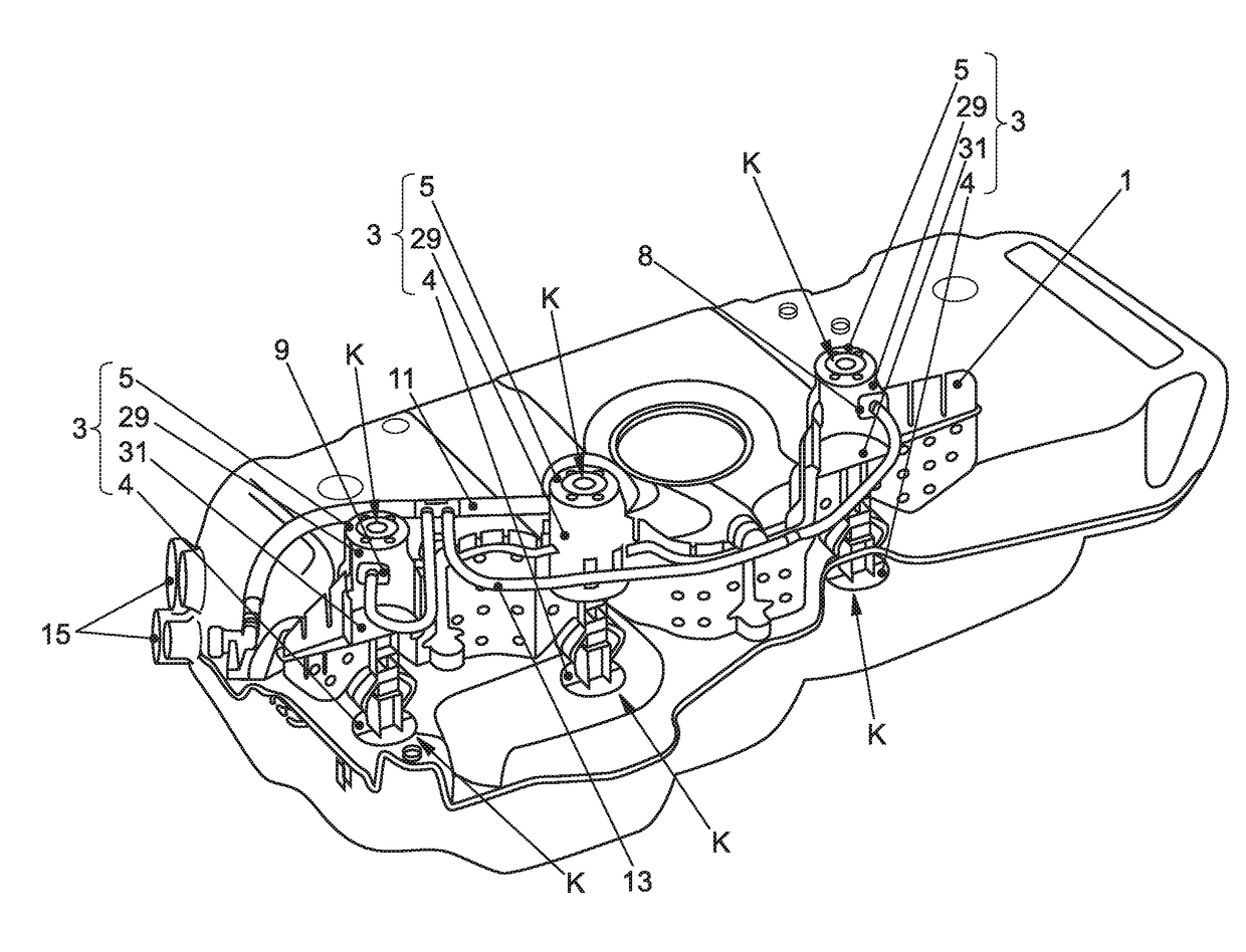
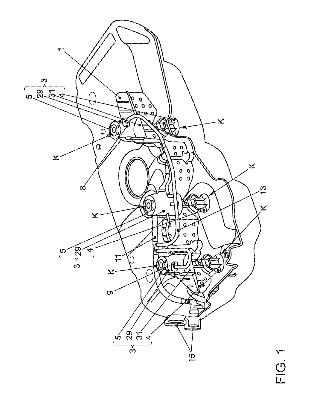
[0032]FIG. 1 is a perspective view of a fuel tank made from a thermoplastic resin, which is designed as a blow-molded plastic hollow member. In the interior of the fuel tank, an elongated baffle wall 1 is arranged, which divides the interior of the tank. The baffle wall 1 is also manufactured from a thermoplastic resin, for example in an injection-molding process. As can be seen from FIG. 1, a total of three mutually spaced vertical, columnar strut arrangements 3, which are supported in a vertical direction between the upper and lower fuel tank inner sides, are integrated in the baffle wall 1. For this purpose, each of the strut arrangements 3 of the baffle wall 1 has lower supporting legs 4 and upper supporting legs 5, which are supported on the respective fuel tank interior side, under the formation of node locations K. The node locations K are designed to be rigid to provide the fuel tank and the baffle wall 1 arranged therein with sufficient dimensional stability.

[0033]In FIG. 1...


PUM


Abstract

A fuel tank and a method for producing a fuel tank for a motor vehicle. The fuel tank is designed as a blow-molded hollow plastic member, into the interior of which a functional component support is introduced. The support, to which functional components, such as a fuel pump, a level indicator or valves can be secured, includes at least one supporting leg to be supported on an inner face of the hollow plastic member delimiting the interior thereof. The supporting leg of the functional component support is designed to include a connection point to which a functional component can be connected.

Description

[0001]This nonprovisional application is a continuation of International Application No. PCT / EP2015 / 071812, which was filed on Sep. 23, 2015, and which claims priority to German Patent Application No. 10 2014 222 142.0, which was filed in Germany on Oct. 30, 2014, and German Patent Application No. 10 2015 207 835.3, which was filed in Germany on Apr. 28, 2015, and which are all herein incorporated by reference.BACKGROUND OF THE INVENTION[0002]Field of the Invention[0003]The invention relates to a fuel tank for a motor vehicle and to a method for producing such a fuel tank.[0004]Description of the Background Art[0005]According to conventional practice, such fuel tanks can be produced from a thermoplastic resin, for example by extrusion blow molding or by welding injection-molded half-shells made of thermoplastic resin. In the interior of such a fuel tank, functional components of the fuel system can be accommodated, as a result of which the space requirement outside the fuel tank is ...

Claims


Application Information

Patent Timeline
IPC IPC(8): B60K15/03B29C49/20B29C49/04
CPCB60K15/03177B29C49/04B29C49/20B60K2015/0344B29K2105/258B60K2015/03493B29C2049/2013B29L2031/7172B29K2101/12B60K2015/0346B60K2015/03467B29C48/0017
Inventor DIESTELHORST, AXEL
Owner VOLKSWAGEN AG
Why Eureka
Try Eureka