
Compression fixation system

a compression fixation and locking assembly technology, applied in the direction of internal osteosynthesis, internal osteosynthesis, osteosynthesis devices, etc., can solve the problems of bone loss/damage, cost associated with inventory to provide the number of components,

Active Publication Date: 2017-08-24
NUMAGENESIS LLC
View PDF1 Cites 5 Cited by
  • Summary
  • Abstract
  • Description
  • Claims
  • Application Information

AI Technical Summary

Benefits of technology

The patent text describes a problem with existing fixation systems used to join bones together. These systems can cause damage to the bones, require difficult placement, and may not provide a reliable fix. The invention provided in this patent helps to overcome these issues and provides an easy-to-use, adjustable, and highly reliable and precise locking system for bones. This system minimizes the risk of complications and allows for the proper amount of compression between bones.

Problems solved by technology

There are challenges with all of these, which include, for example, imprecise compression and fixation, protrusion of the fixation element from bone into tissue (screw heads, twists of wires), bone loss / damage due to size of fixation element and damage to bone (for example, thread stripping of screws within bone), and costs associated with inventory to provide the number of components needed to meet size ranges of fractures.
However, it remains a problem in the art to achieve fixation of relatively small bones using low profile fixation components that are capable of fine adjustment to placement and tensioning, are relatively simple to manipulate and are adjustable and / or removable post fixation.

Method used


Image

  • Compression fixation system
  • Compression fixation system
  • Compression fixation system

Examples


example 3

Instruments for Engaging and Tensioning System Components

[0071]The compression fixation system also includes instruments for assembling and locking the coupling component and locking assembly components.

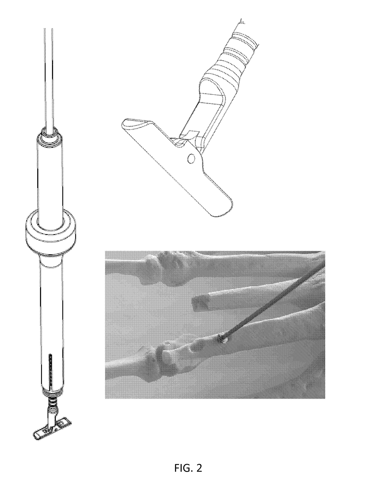
[0072]One exemplary instrument includes a locking assembly insertion tool, shown in perspective view in FIG. 9. The insertion tool operates to maintain orientation and alignment of the locking assembly components and the coupling component and can be actuated to reduce and lock the locking assembly components, or loosen and unlock the locking assembly for adjustment during healing or post treatment removal of the system. Referring again to the drawings, FIG. 9-FIG. 13 show alternate views of the components of an exemplary embodiment of a locking assembly insertion tool for achieving placement, component reduction, friction tensioning, locking and unlocking of a locking assembly as described herein. Referring now to FIG. 9, the insertion tool includes two nesting elongate sleeves, eac...

example 4

Threaded Torsional Locking Compression Fixation System

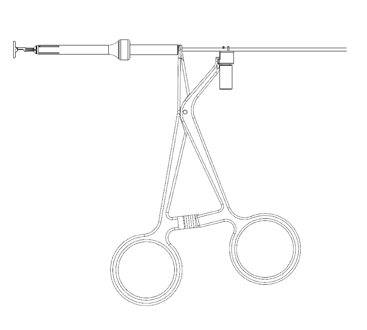
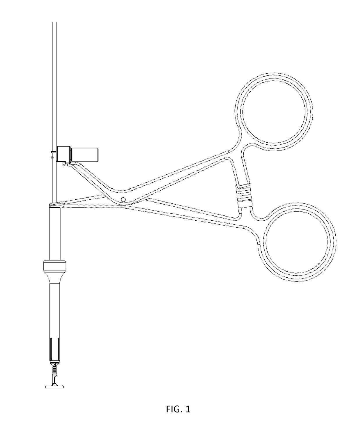
[0079]Referring now to FIG. 16-FIG. 18, various views of an alternate embodiment of a compression fixation system are shown. FIG. 16 shows a side view of a fully assembled compression fixation system engaged with coupling component tensioning and locking assembly inserter instruments.

[0080]The compression fixation system includes a coupling component that is selected from suitable wire and other bone pins and similar rod type devices, such as, for example K-wire. The coupling component is adapted at a first end, intended to be most distal to the operator, with an anchor portion for fixation within or on a distal outer surface of a first bone element. The coupling component is further adapted at a second end, intended to be most proximal to the operator, with a locking assembly receiver portion that is generally rectilinear. In various embodiments, at least the proximal portion of the coupling component is substantially rectilinea...


PUM


Abstract

The invention is directed in various aspects to a compression fixation system that includes coupling components and locking assemblies for connecting two or more separate elements in a fixed arrangement. For example, the system is useful for connecting and compressing two or more elements selected from bones and bone fragments. The system includes a substantially linear coupling component, such as, for example, a Kirschner Wire (“K-Wire”) and locking assembly elements that engage with the coupling component in a coaxial orientation. The coupling component includes at least a linear portion and an anchor portion, the anchor portion configured to be fixed within or adjacent to a first one of the elements to be connected and the linear portion configured to be fixed adjacent to a second one of the elements to be connected, where the locking assembly is attached coaxially with and locked against the second element to achieve compression and fixation.

Description

RELATED APPLICATIONS[0001]This application claims the benefit under 35 U.S.C. §119 (e) to U.S. Provisional Application Ser. No. 62 / 073,968 filed Nov. 1, 2015, the entirety of which is incorporated herein by reference.FIELD OF INVENTION AND BACKGROUND[0002]The invention relates generally to a locking assembly and a compression fixation system for fixing two or more elements together and to maintain, and optionally adjust a desired degree of compression across the two or more objects. The system is suitable, for example, for connecting and compressing two or more elements selected from bones and bone fragments. The system includes a substantially linear coupling component, and a locking assembly that engages with a locking assembly-receiving portion the coupling component in a generally coaxial orientation.[0003]The invention is described herein below in relation to bone fractures, which is but an example of the useful application of the invention. One skilled in the art will apprecia...

Claims


Application Information

Patent Timeline
IPC IPC(8): A61B17/88A61B17/68
CPCA61B17/885A61B17/8872A61B17/8866A61B17/683A61B17/68A61B17/8869
Inventor KUKLA, ROBERTVON AMSBERG, MARCBINDER, LAWRENCE
Owner NUMAGENESIS LLC
Learn More