Bucket Funnel

Active Publication Date: 2017-08-24
DEGRAAF 3RD MARTIN CHRISTIAN
View PDF14 Cites 1 Cited by
  • Summary
  • Abstract
  • Description
  • Claims
  • Application Information

AI Technical Summary

Benefits of technology

The patent is a guide to understand a bucket funnel system and its use for dispensing fluids. The system includes a cone-shaped funnel attached to a bucket. The funnel has a semicircular lower edge that forms an inlet for the fluid, with a funnel rim and a hopper opening. The funnel is attached to the bucket using tabs, an inner apron, and a release clip for a tight seal. The nozzle opening of the system can vary depending on the viscosity and properties of the fluid being dispensed. The target location of the fluid bead is controlled, resulting in a uniform and well-controlled deposit. The system provides a stable flow rate of fluid even at different head pressures and ensures a controlled bead location.

Problems solved by technology

The system is not effective, however, if one wishes to transfer a more viscous fluid, such as caulking, from a container to a surface below as a continuous steady stream of material.
This causes large changes in flow rate due to the wide open top lip.

Method used


Image

  • Bucket Funnel
  • Bucket Funnel
  • Bucket Funnel

Examples


example 1

[0026]FIGS. 6 and 7 are illustrations 600, 700 of a worker 612 pouring fresh concrete 616 from a 5 liter bucket 620 through an alternative embodiment of a bucket funnel 630. In FIG. 6, the worker has just interrupted filling a first channel 605 cut in a first concrete slab 602. The worker is joining the first concrete slab to a second concrete slab 604. The first channel is cut from the first slab to the second slab. A second channel 606 is similarly cut from the first slab to the second slab. A steel bar 608 which traverses the slabs has been placed in each of the channels. Fresh concrete is being poured 610 into each channel to lock in the steel bars thus joining the slabs together.

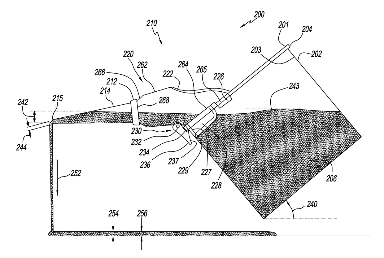
[0027]The bucket funnel comprises a nozzle 634 mounted on a funnel body 632. An inner apron 648 extends down from the funnel body. A flexible skirt 650 extends outward from the inner apron to press against and form a seal with the inner wall 654 of the bucket. The flexible skirt forms a seal despite the...


PUM


Abstract

A bucket funnel has a funnel body which clips onto a bucket with a top flange. The funnel body has a semicircular lower edge which has about the same radius of curvature as the bucket, but only extends about halfway around. There are outer tabs with inward facing channels at the ends of the lower edge of the funnel body to clip into the flange of the bucket. There is also a spring loaded release clip at about the middle of the lower edge to clip onto the outer flange of the bucket. An inner apron extends down from the lower edge of the funnel body to form a seal against the inner wall of the bucket. An interchangeable conical nozzle attaches to the funnel body for dispensing of fluids of various viscosities, such as glue, paint or fresh concrete.

Description

TECHNICAL FIELD[0001]The inventions described herein are in the field of dispensing nozzles.BACKGROUND ART[0002]There is a long felt need for an effective way to transfer liquids from containers. FIG. 1 illustrates side view of a prior art pouring spout system 100. The system comprises a pouring spout 110 fitted into the top of a paint can 102. An example of this system is the Allway®“Spout and Can Cover”. The pouring spout comprises a lower tapered circular skirt 112 and an upper rim 114. One end of the rim comprises a wide lip 116. The circular tapered skirt is wedged into the internal gutter 104 of the paint can to form a seal. The skirt may be made of plastic. If the paint can is tipped at an angle 124, the paint 106 within the can flows onto the rim, overflows the lip and descends as a stream 132.[0003]This system is effective for transferring runny fluids from a can to another container. The system is not effective, however, if one wishes to transfer a more viscous fluid, such...

Claims


Application Information

Patent Timeline
IPC IPC(8): B67C11/02B65D25/50B65D25/48
CPCB67C11/02B65D25/50B65D25/48B65D25/40B65D25/42B67C11/00B67C11/04
Inventor DEGRAAF 3RD, MARTIN CHRISTIANREPP, TIMOTHY CORCORAN
Owner DEGRAAF 3RD MARTIN CHRISTIAN
Why Eureka
Try Eureka