
Magnet for Head and Extremity Imaging

a superconducting magnet and head technology, applied in the direction of superconducting magnets/coils, measurement devices, instruments, etc., can solve the problems of claustrophobia, expensive whole body magnets used in producing images, and many people suffering from claustrophobia

Active Publication Date: 2017-08-24
MAGNETICA
View PDF6 Cites 4 Cited by
  • Summary
  • Abstract
  • Description
  • Claims
  • Application Information

AI Technical Summary

Benefits of technology

The invention is about a magnet system that allows for access to a device through both the shoulder and the smaller part of the body. The design of the magnet also takes into account the force on the coils, to minimize any damage. This allows for greater flexibility and ease of access for medical procedures.

Problems solved by technology

Not surprisingly, many people suffer from claustrophobia when placed in such a space.
Moreover, the large distance between the portion of the subject's body which is being imaged and the end of the magnet system means that physicians cannot easily assist or personally monitor a subject during an MRI procedure.
Due to their large size, such whole body magnets are expensive for use in producing images of small sizes of objects, such as, heads, extremities and neonates, etc.
Those magnets have limited applications and are mostly suitable for brain imaging.
They are not useful for extremity imaging such as the imaging of knee joints as the joint cannot reach to the imaging zone for most patients due to the long distance to the dsv from the end and the difficultly of placing and accommodating the other leg, for example.
However, the magnet of U.S. Pat. No. 5,307,039 still has the disadvantages of being a relatively large magnet but only produces a field strength of around 0.5 T. While the magnet of U.S. Pat. No. 7,498,810 is smaller, and provides access from both ends, its configuration is particularly suited for extremity imaging rather than imaging of human heads.

Method used


Image

  • Magnet for Head and Extremity Imaging
  • Magnet for Head and Extremity Imaging
  • Magnet for Head and Extremity Imaging

Examples


example 1 (

3.0 T Magnet)

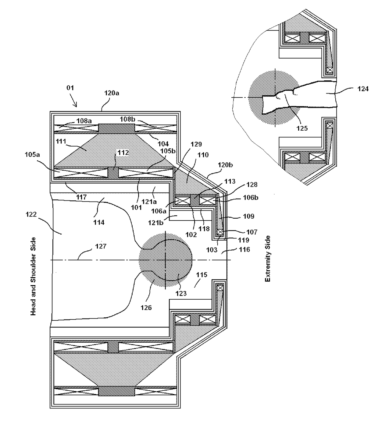
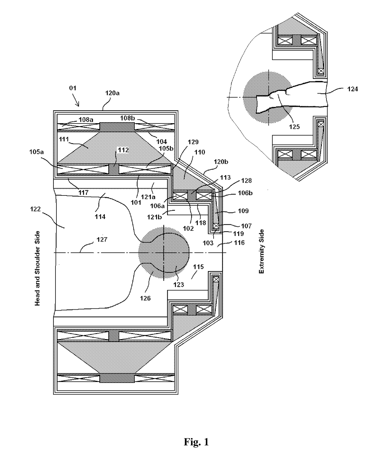
[0072]FIG. 5 schematically illustrates a superconducting magnet according to a first embodiment of the present invention. The magnet employs five primary coils (two coils at the first former segment, two other coils at the second former segment and one at the third former segment) and one shield coil. In broad overview, the magnet has a cold bore length of approximately 0.92 meters and a cold bore largest inner radius and smallest inner radius of approximately 0.46 and 0.13 meters, respectively. The magnet has a dsv which is approximately spherical with a diameter of approximately 27 centimetres.

[0073]FIG. 5 shows the magnet and the field within the dsv. FIG. 6 shows the calculated stray external fields and axial magnetic field generated by the magnet. FIG. 7 shows the calculated magnitudes of the total magnetic field generated by the magnet within the magnet's various coils. FIG. 8 shows the calculated magnitudes of the total electromagnetic forces generated by the mag...

example 2 (

1.5 T Magnet)

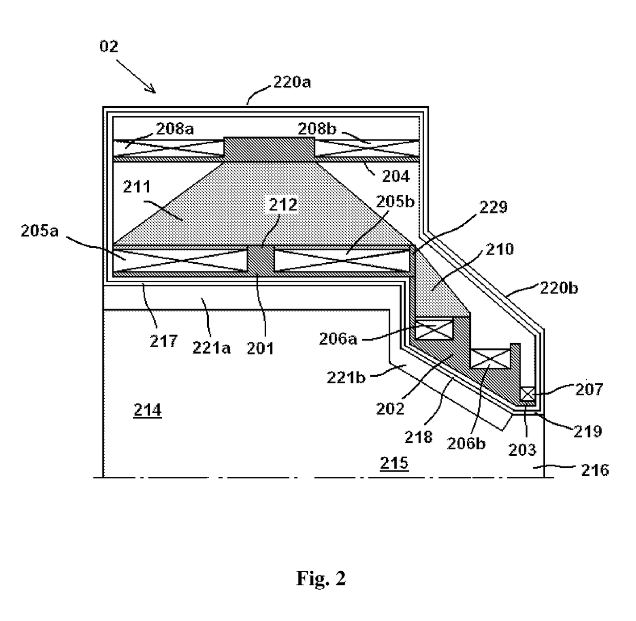
[0075]FIG. 10 schematically illustrates a 1.5 T superconducting magnet design using a structure according to a second embodiment of the invention.

[0076]The magnet employs five primary coils (two coils at the first former segment, two other coils at the second former segment and one at the third former segment) and two shield coils. In broad overview, the magnet has a cold bore length of approximately 0.78 meters and a cold bore largest inner radius and smallest inner radius of approximately 0.45 and 0.16 meters, respectively. The magnet has a dsv which is approximately elliptical with an axial diameter of approximately 20 centimetres and a radial diameter of approximately 30 centimetres.

[0077]FIG. 10 shows the magnet and the field within the dsv. FIG. 11 shows the calculated stray external fields and axial magnetic field generated by the magnet. FIG. 12 shows the calculated magnitudes of the total magnetic field generated by the magnet within the magnet's various coils....


PUM


Abstract

A magnetic resonance imaging (MRI) system uses a superconducting magnet having a primary coil structure and a shielding coil layer. The primary coil structure comprises at least three sets of coils with significantly different inner diameters, forming a three-bore magnet structure. The three bores are coaxially aligned with a longitudinal axis, with the largest diameter first bore on one side of the magnet and the smallest diameter third bore on another side of the magnet, as well as a medium diameter second bore located axially between the first and the third bores. The first bore allows access for the head and shoulders and permits the head to enter into the second bore for imaging, while the patient's extremities (hands, legs) may access through the third bore for producing images of the extremity joints. The magnet may also be used for other specialist imaging where use of a whole-body MRI is unwarranted, such as the imaging of neonates. Reinforcing plates can be connected between coil formers to withstand the forces generated by the high magnetic fields.

Description

FIELD OF THE INVENTION[0001]The present invention relates to compact, shielded asymmetric superconducting magnets for producing homogeneous magnetic fields (B0 fields) for use in specialist magnetic resonance imaging (MRI) applications. The magnets have portions of different bore diameter and are configured for producing images of the head and extremity joints of a subject, as well as neonatal images, in an inexpensive manner.BACKGROUND OF THE INVENTION[0002]Magnetic resonance imaging was introduced in the 1980s, and has developed into a major global imaging modality.[0003]Clinical MRI depends for its success on the generation of strong and pure magnetic fields. A major specification of the static field in MRI is that it has to be substantially homogeneous over a predetermined region, known in the art as the “diameter spherical imaging volume” or “dsv”. Errors less than 20 parts per million peak-to-peak (or 10 parts per million rms) are typically required for the dsv.[0004]MRI equip...

Claims


Application Information

Patent Timeline
IPC IPC(8): G01R33/3815G01R33/421H01F6/06G01R33/385
CPCG01R33/3815H01F6/06G01R33/421G01R33/385
Inventor WEI, RIYULIU, FENGCROZIER, STUART
Owner MAGNETICA
Learn More