Magnets for use in magnetic resonance imaging

a magnetic resonance imaging and magnet technology, applied in wave based measurement systems, instruments, reradiation, etc., can solve the problems of high cost, high specialised and expensive infrastructure, and many people suffering from claustrophobia, so as to reduce the net force

Active Publication Date: 2013-04-16
NMR HLDG NO 2
View PDF13 Cites 8 Cited by
  • Summary
  • Abstract
  • Description
  • Claims
  • Application Information

AI Technical Summary

Benefits of technology

[0022]The above described extremity magnet has the desirable characteristics of relatively strong field strength, small size and relatively large homogeneous dsv.
[0024]Preferably, force balancing is used in the design of the magnet to minimize the net forces on the coils, and in particular, the end coils in the primary coil structure, thereby substantially reducing the need for support former material external to the end coils. In implementing the step of force balancing, Maxwell forces are included in the error function to be minimized.

Problems solved by technology

Not surprisingly, many people suffer from claustrophobia when placed in such a space.
Standard 1.5 T MRI whole body scanners, due to their size, weight, fringe field and power needs, demand highly specialised and expensive infrastructure before they can be installed, including development of separate multi-room imaging suites.
These requirements mean that in most cases, only larger hospitals or substantial imaging clinics can afford to install such systems and offer MRI as a diagnostic modality to patients.
Longer magnets require more shielding and larger shielded rooms for such safe usage, thus leading to higher costs.
While extremity MRI systems have a number of advantages to the subject and the operator, they represent a challenge in terms of the space available for the various coils making up the magnet and in terms of cooling those superconducting coils.
A major difficulty in realizing a superconducting magnet is to produce a large imaging dsv (of the required homogeneity) when the magnet length is reduced, while ensuring the superconducting wires can be used safety and efficiently.
The low field nature of the current smaller MRI systems on offer is a major disadvantage to their use.
According to the American College of Rheumatology, ‘the low-field MRI systems are unable to obtain the SNR of high-field MRI systems for images of similar spatial resolution’.
Low field systems generally have longer image acquisition times, which can be problematic for procedures requiring contrast agents, since for extremity procedures, intravenously injected contrast agents can diffuse into the joint fluid in a period of minutes.

Method used


Image

  • Magnets for use in magnetic resonance imaging
  • Magnets for use in magnetic resonance imaging
  • Magnets for use in magnetic resonance imaging

Examples


example 1

1.5 T Magnet

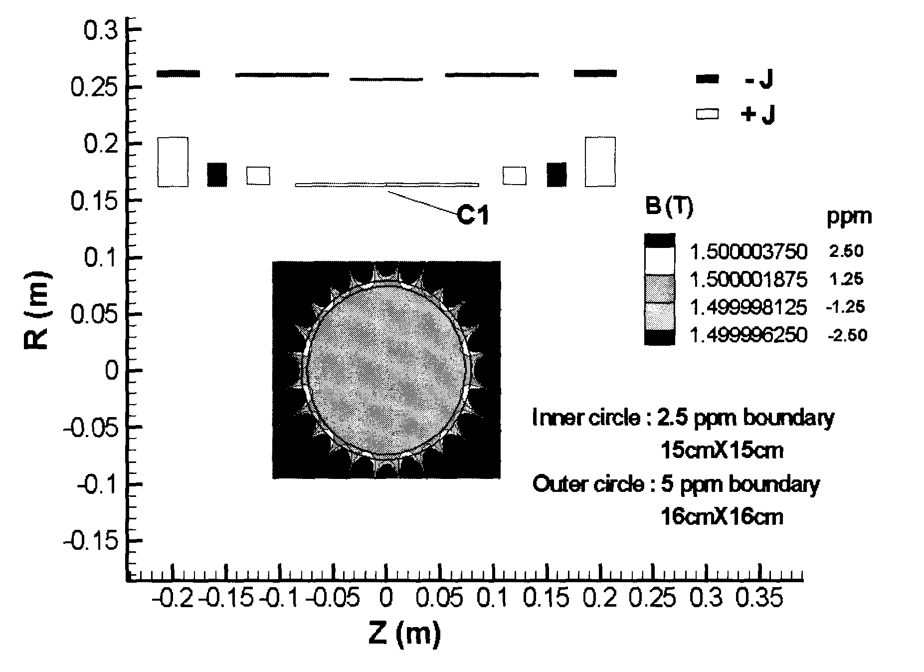
[0060]This example, shown schematically in FIG. 1, illustrates a superconducting magnet of the present invention. In broad overview, the magnet employs twelve coils and has a cold bore length and a cold bore inner radius of approximately 0.43 and 0.165 meters, respectively. On the primary windings of the magnet, all of the coils are wound in the same direction (i.e. have the same polarity) apart from the coils second from the ends, i.e. those two coils approximately centered at 0.16 m from the centre. These coils are wound in the opposite direction to all others on the primary (i.e. have reverse polarity).

[0061]The central coil on the primary winding (i.e. that coil spanning the z=0 position, denoted C1) is longer than the others (and comprises approximately 38% of the total magnet length). This feature, when combined with the topology of the other coils, results in improved homogeneity compared to other coil configurations for a magnet of the same overall length. There ...

example 2

3 T Magnet

[0067]This example, shown schematically in FIG. 5, illustrates a 3 T superconducting magnet design using a structure according to a second embodiment of the invention.

[0068]As shown in FIG. 5, the coil structure is less than 0.5 meter in total length while a homogeneous dsv is generated over an ellipse of major axis 17 cm and minor axis approximately 15 cm wherein the homogeneity of the dsv varies by less than + / −5 ppm over that volume. The magnet uses the same topology as that in example 1, where the coils next to the end coil on the primary are of opposite polarity to all others in the primary coil set. The middle coil in this example extends approximately 45% of the total length of the coil structure and this feature again provides the advantage when combined with the other features of producing a relatively large and useful imaging region.

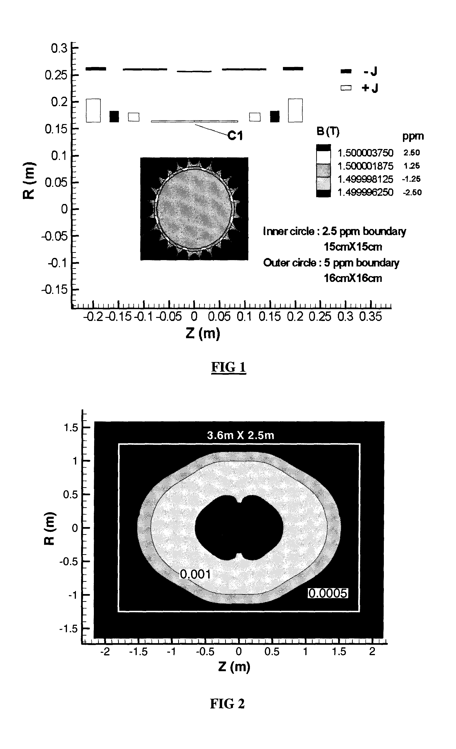
[0069]The stray fields in this magnet are well controlled, being approximately 1.8 m and 1.25 m in the axial and radial directions r...


PUM


Abstract

A magnetic resonance system uses a shielded superconducting magnet to produce a dsv useful for specialist imaging in an overall short magnet system at field strengths 1.5 Tesla and above. The magnet includes at least a first central coil C1, which has a length of at least 25% of the overall length of the magnet, and is used in concert with a series of symmetric primary coils, at least one set of which carry current in a direction opposite to that of the central coil. Force balancing is advantageously used in the design of the coils. The primary coils are shielded by at least one shielding coil, which carries current in a direction opposite to the majority of the primary coils. The magnet resonance system can be used for orthopedic imaging.

Description

I. FIELD OF THE INVENTION[0001]The present invention relates to short, shielded superconducting magnets for producing substantially homogeneous magnetic fields (B0 fields) for use in magnetic resonance imaging applications. The magnets are particularly well-suited for use in specialist magnetic resonance imaging, and especially for use in producing images of extremity joints of a subject, e.g., a subject's knee, ankle or wrist.II. BACKGROUND OF THE INVENTION[0002]Magnetic Resonance Imaging (MRI) was introduced in the 1980s, and has developed into a major global imaging modality with current sales of approximately 3,000 scanners worldwide per annum.[0003]Clinical MRI depends for its success on the generation of strong and pure magnetic fields. A major specification of the static field in MRI is that it has to be substantially homogeneous over a predetermined region, known in the art as the “diameter spherical imaging volume” or “dsv.” Errors or variation of less than 20 parts per mil...

Claims


Application Information

Patent Timeline
Patent Type & Authority Patents(United States)
IPC IPC(8): G01V3/00
CPCG01R33/3815G01R33/421
Inventor CROZIER, STUARTZHAO, HUAWEILIU, FENG
Owner NMR HLDG NO 2
Why Eureka
Try Eureka