Vehicle, image display device, vehicle control method, and image display method

a technology for image display devices and vehicles, applied in the direction of pedestrian/occupant safety arrangements, navigation instruments, instruments, etc., can solve the problem of inability to display the information of vehicles, and achieve the effect of convenient vehicle, rapid response, and reduced power consumption of vehicles

Active Publication Date: 2017-08-31
HONDA MOTOR CO LTD
View PDF3 Cites 4 Cited by
  • Summary
  • Abstract
  • Description
  • Claims
  • Application Information

AI Technical Summary

Benefits of technology

[0023]According to the above-described aspect <3>, it is possible to prevent the user from forgetting a parking position after parking because it is possible to guide the user to the location of a vehicle after the user turns off the power supply of the vehicle and gets out of the vehicle. Therefore, according to the above-described <3>, a convenient vehicle can be provided.
[0024]According to the above-described aspect <4>, power is supplied to each unit of the vehicle for a predetermined time after the power supply of the vehicle is turned off. Thereby, according to the above-described state <4>, a convenient vehicle can be provided to a user because information of the vehicle can be provided to the user even in a

Problems solved by technology

However, if technology disclosed in Patent Literature 1 is used in the image display device which displays information of a vehicle, it is possible to di

Method used


Image

  • Vehicle, image display device, vehicle control method, and image display method
  • Vehicle, image display device, vehicle control method, and image display method
  • Vehicle, image display device, vehicle control method, and image display method

Examples


first embodiment

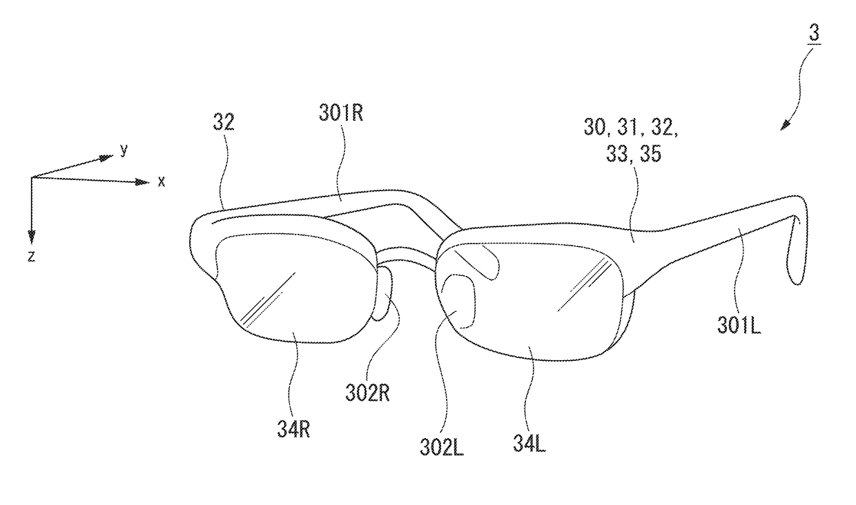
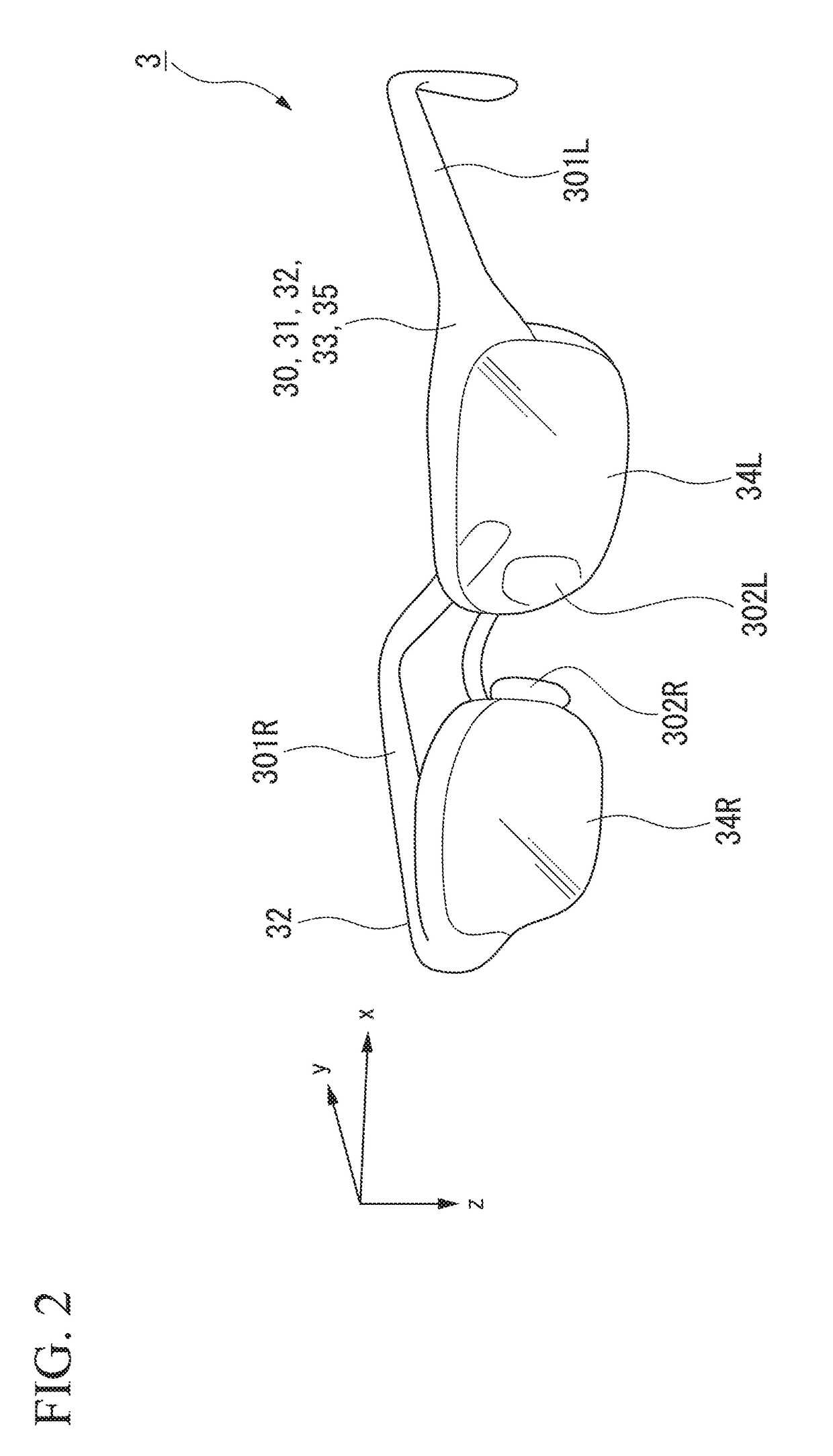
[0038]In the present embodiment, an example of an eyeglass type head-mounted display (hereinafter referred to as an HMD) serving as an image display device will be described.

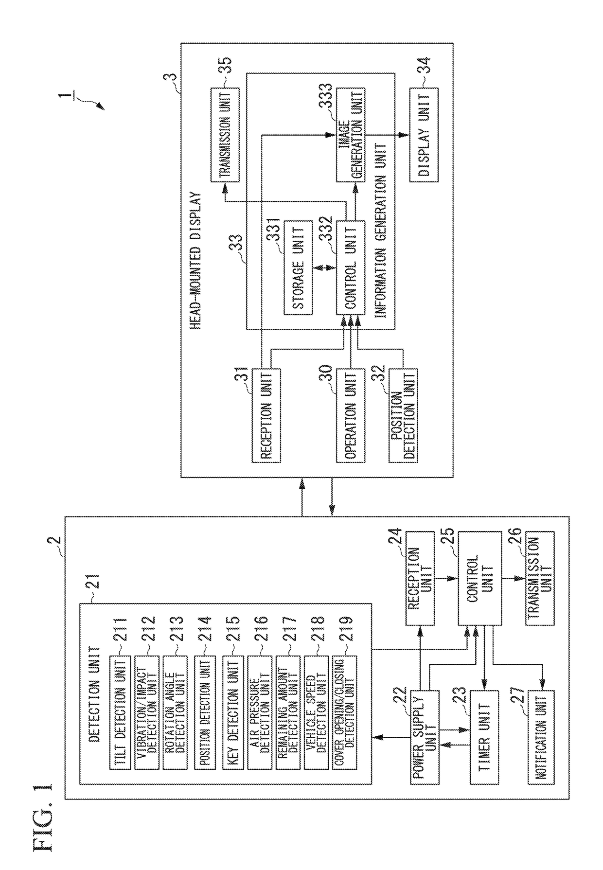
[0039]FIG. 1 is a block diagram illustrating a schematic configuration of a vehicle detection system 1 according to the first embodiment.

[0040]As illustrated in FIG. 1, the vehicle detection system 1 includes a vehicle 2 and an HMD 3 (an image display device).

[0041]Also, the vehicle 2 and the HMD 3 perform communication using, for example, a short-range wireless communication standard. The short-range wireless communication standard is, for example, communication of a Bluetooth (registered trademark) low energy (LE) (hereinafter referred to as BLE) standard.

[0042]First, the vehicle 2 will be described.

[0043]The vehicle 2 includes a detection unit 21, a power supply unit 22, a timer unit 23, a reception unit 24, a control unit 25, a transmission unit 26, and a notification unit 27. Also, the detection unit 21 inc...

second embodiment

[0130]FIG. 8 is a block diagram illustrating a schematic configuration of a vehicle detection system 1A according to the present embodiment.

[0131]As illustrated in FIG. 8, the vehicle detection system 1A includes a vehicle 2, an HMD 3 (an image display device), and a terminal 4 (an image display device). Also, the same reference signs are used in functional units having the same functions as those of the vehicle detection system 1 in the first embodiment and description thereof will be omitted.

[0132]The vehicle 2 and the terminal 4 or the HMD 3 and the terminal 4 perform communication using, for example, a short-range wireless communication standard. The short-range wireless communication standard is, for example, communication of a BLE standard. Also, if the vehicle 2, the HMD 3, and the terminal 4 perform communication, the vehicle 2 is paired with the HMD 3 and the terminal 4. If the HMD 3 and the terminal 4 perform communication, the HMD 3 is paired with the terminal 4.

[0133]As ...


PUM


Abstract

A vehicle includes a detection unit configured to detect a state of the vehicle, a transmission unit configured to transmit information based on a result of the detection performed by the detection unit to an image display device, and a control unit configured to change information to be transmitted to the image display device when a power supply of the vehicle has changed from an on state to an off state.

Description

CROSS-REFERENCE TO RELATED APPLICATION[0001]Priority is claimed on Japanese Patent Application No. 2016-038291, filed Feb. 29, 2016, the content of which is incorporated herein by reference.BACKGROUND OF THE INVENTION[0002]Field of the Invention[0003]The present invention relates to a vehicle, an image display device, a vehicle control method, and an image display method.[0004]Description of Related Art[0005]Recently, image display devices which are mounted on a head portion for use have been developed. These image display devices are of a non-transparent type that blocks vision and a transparent type that does not block vision. With the non-transparent type, only an image is displayed on a display unit. Thus, a user can view only the image. In the transparent type, a display unit is, for example, a half-mirror. Thus, the user can view the appearance of an external world and an image.[0006]As disclosed in PCT International Publication No. WO2014 / 128809 (hereinafter, Patent Literatur...

Claims


Application Information

Patent Timeline
IPC IPC(8): G07C5/08B60C23/02G01C21/36B60R21/013
CPCG07C5/0825G07C5/0808B60R2021/01095B60C23/02G01C21/3661B60R21/013G07C5/008G07C5/0858
Inventor MIZUNO, KUNIHIROFUKANO, SHIRO
Owner HONDA MOTOR CO LTD
Why Eureka
Try Eureka