Non-pneumatic tire

a technology of non-pneumatic tires and treads, which is applied in the direction of tyre parts, tyre tread bands/patterns, transportation and packaging, etc., to achieve the effect of limiting the wear of the tread member even after us

Inactive Publication Date: 2017-09-07
BRIDGESTONE CORP
View PDF10 Cites 8 Cited by
  • Summary
  • Abstract
  • Description
  • Claims
  • Application Information

AI Technical Summary

Benefits of technology

[0009]According to a non-pneumatic tire of the present invention, variation of a magnitude of a ground contact pres...

Problems solved by technology

The occurrence of a puncture of a pneumatic tire which has an inside thereof filled with pre...

Method used


Image

  • Non-pneumatic tire
  • Non-pneumatic tire
  • Non-pneumatic tire

Examples


first embodiment

Modified Example of First Embodiment

[0093]In the above-described first embodiment, the outer peripheral surface of the tread member 16 may be formed in a shape protruding outward in the tire radial direction in the cross-sectional view in the tire width direction H.

[0094]FIGS. 8 and 9 show a modified example of the first embodiment.

[0095]In the example shown in FIGS. 8 and 9, a plurality of curved surface parts 41 to 43 of an outer peripheral surface of a tread member 16 are connected to each other in a tire width direction H with no step therebetween and are formed in shapes protruding outward in a tire radial direction in a cross-sectional view in the tire width direction H. To be specific, the outer peripheral surface of the tread member 16 is formed in a curved surface shape formed to project outward in the tire radial direction when an entire non-pneumatic tire 1 is viewed.

[0096]The outer peripheral surface of the tread member 16 is constituted of three curved surface parts: ce...

second embodiment

[0120]A second embodiment related to the present invention will be described.

[0121]The second embodiment is different from the first embodiment in that, while the first divided case body 31 and the second divided case body 32 divided in the tire width direction H are provided in the first embodiment, an exterior body 61, a ring-shaped body 62, and connecting members 63 are not divided in a tire width direction H and grooves 57 and 58 of a tread member 16 are different in the second embodiment.

[0122]Note that constituent elements of the second embodiment that are the same as those of the first embodiment are denoted with the same reference numerals, and descriptions thereof are omitted.

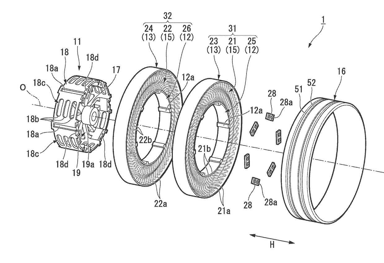
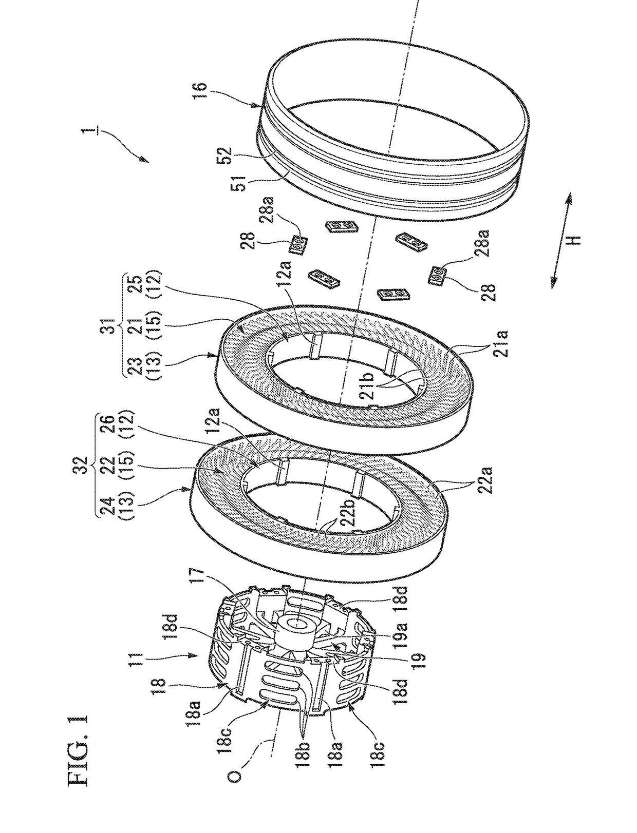
[0123]As shown in FIG. 10, a non-pneumatic tire 60 of this embodiment includes a mounting body 11, the exterior body 61, the ring-shaped body 62, the connecting members 63, and the tread member 16.

[0124]A width of the exterior body 61 in the tire width direction H is the same as that when the first ext...


PUM


Abstract

The present invention is provided with: a mounting body mounted on an axle; a ring-shaped body (13) surrounding the mounting body from an outside in a tire radial direction; a connecting member (15) configured to connect the mounting body and the ring-shaped body (13) such that the mounting body and the ring-shaped body (13) are displaceable; and a cylindrical tread member (16) mounted over the ring-shaped body (13), wherein grooves (51, 52) are formed at an outer peripheral surface of a portion located above and corresponding to a portion of the tread member (16) at which the ring-shaped body (13) and the connecting member (15) are connected.

Description

TECHNICAL FIELD[0001]The present invention relates to a non-pneumatic tire which does not need to be filled with pressurized air when the tire is used.[0002]Priority is claimed on Japanese Patent Application No. 2014-163025, filed Aug. 8, 2014, the content of which is incorporated herein by reference.BACKGROUND ART[0003]The occurrence of a puncture of a pneumatic tire which has an inside thereof filled with pressurized air and is used in a related art is an inevitable problem in terms of a structure thereof.[0004]In order to solve such a problem, in recent years, for example, the non-pneumatic tire disclosed in Patent Document 1 including a mounting body mounted on an axle, a ring-shaped body surrounding the mounting body from an outside in a tire radial direction, a connecting member configured to connect the mounting body and the ring-shaped body so that the mounting body and the ring-shaped body are displaceably connected, and a cylindrical tread member mounted over the ring-shap...

Claims


Application Information

Patent Timeline
IPC IPC(8): B60C7/26B60C7/10
CPCB60C7/26B60C7/102B60C2007/107B60C11/1346B60C9/04B60C7/24B60C11/03B60B9/04B60C7/00B60C7/18B60B9/26B60C11/04B60C11/0083B60C2011/0365B60C7/107
Inventor TAKAHASHI, NARUMIABE, AKIHIKO
Owner BRIDGESTONE CORP
Why Eureka
Try Eureka