Display device

a display device and liquid crystal panel technology, applied in the field of display devices, can solve the problems of insufficient three-dimensional appearance in some cases, inability to effectively use the entire display surface of the liquid crystal panel, and inability to achieve the effect of enhancing depth, enhancing three-dimensional appearance, and increasing far-direction distan

Active Publication Date: 2017-09-07
DENSO CORP
View PDF1 Cites 14 Cited by
  • Summary
  • Abstract
  • Description
  • Claims
  • Application Information

AI Technical Summary

Benefits of technology

[0027]According to the sixth aspect, the back-side real member is expanded by the magnifying lens unit. As a result, an increased far-direction distance is visually recognized between th...

Problems solved by technology

The liquid crystal panel entails physical limitations in terms of the three-dimensional visual recognition of the displayed image, which results in a disadvantage in the form of a planar appearance in comparison to the display devices using the real object.
However, the placement of the decorative ring (real object) on the near si...

Method used


Image

  • Display device
  • Display device
  • Display device

Examples


first embodiment

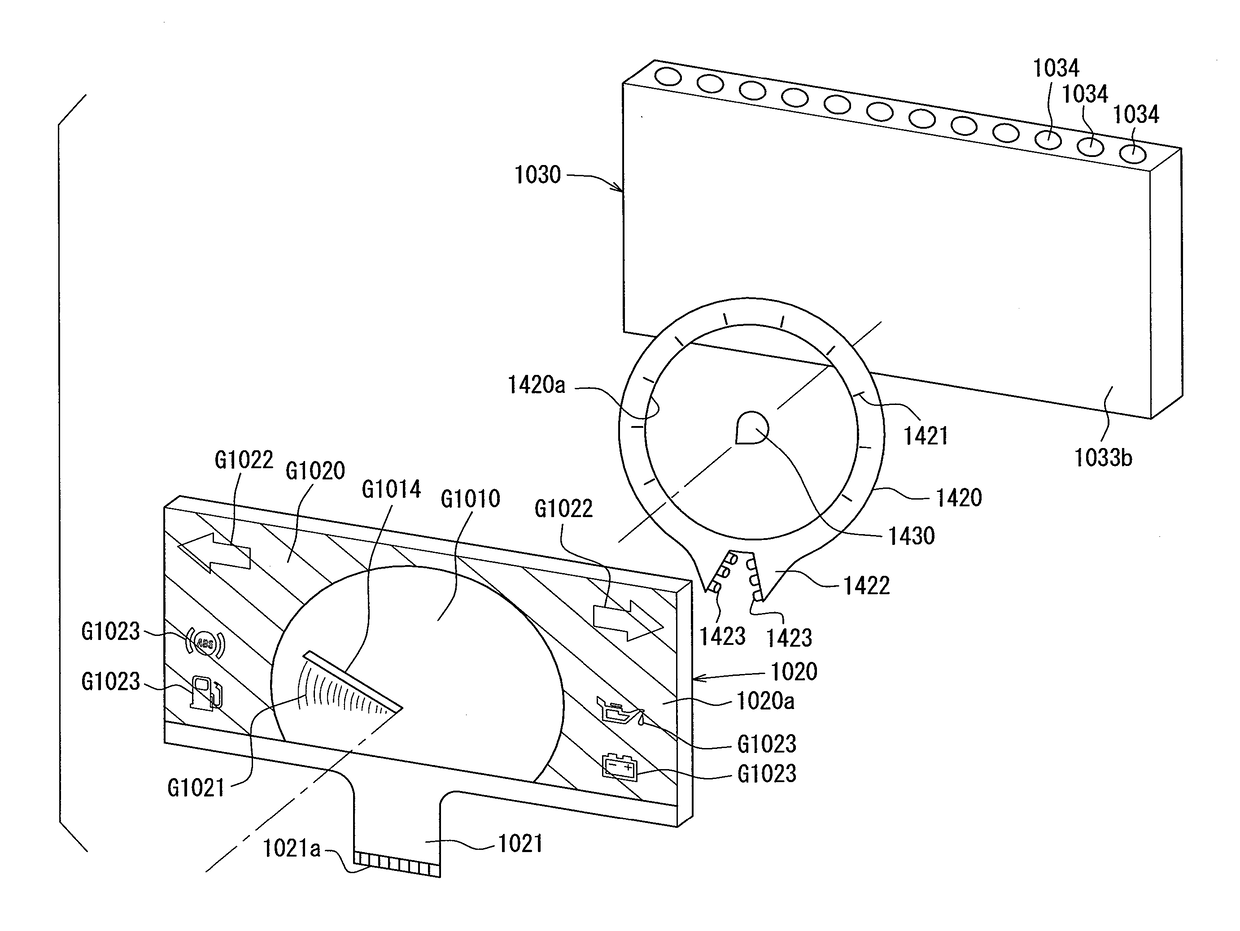
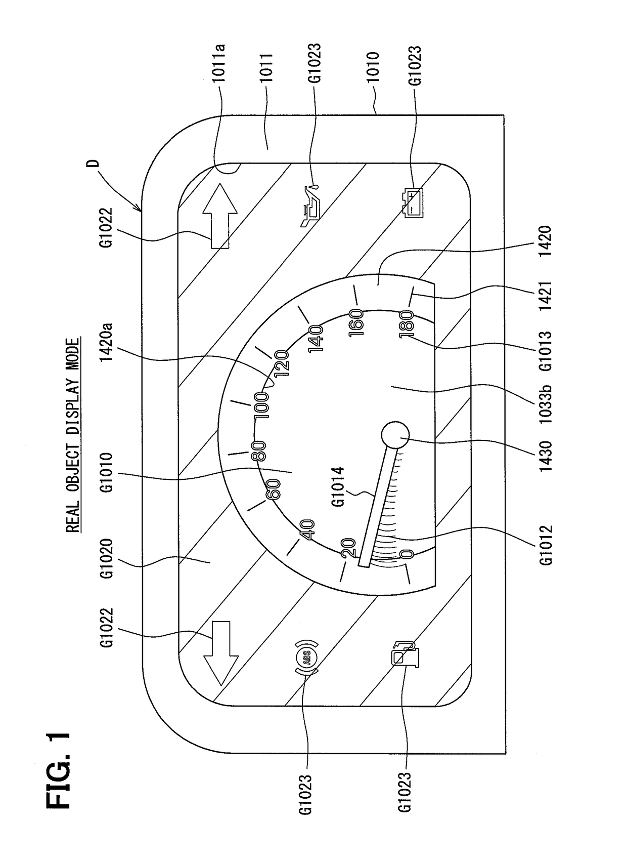
[0098]A display device D illustrated in FIG. 1 is a vehicular display device assembled in an instrument panel in a vehicle. The display device D displays changes in various physical quantities showing states of the vehicle, such as a traveling speed of the vehicle and electric power remaining in an automotive battery, displays the occurrence of various abnormalities in the case of such abnormalities, and displays an effect image.

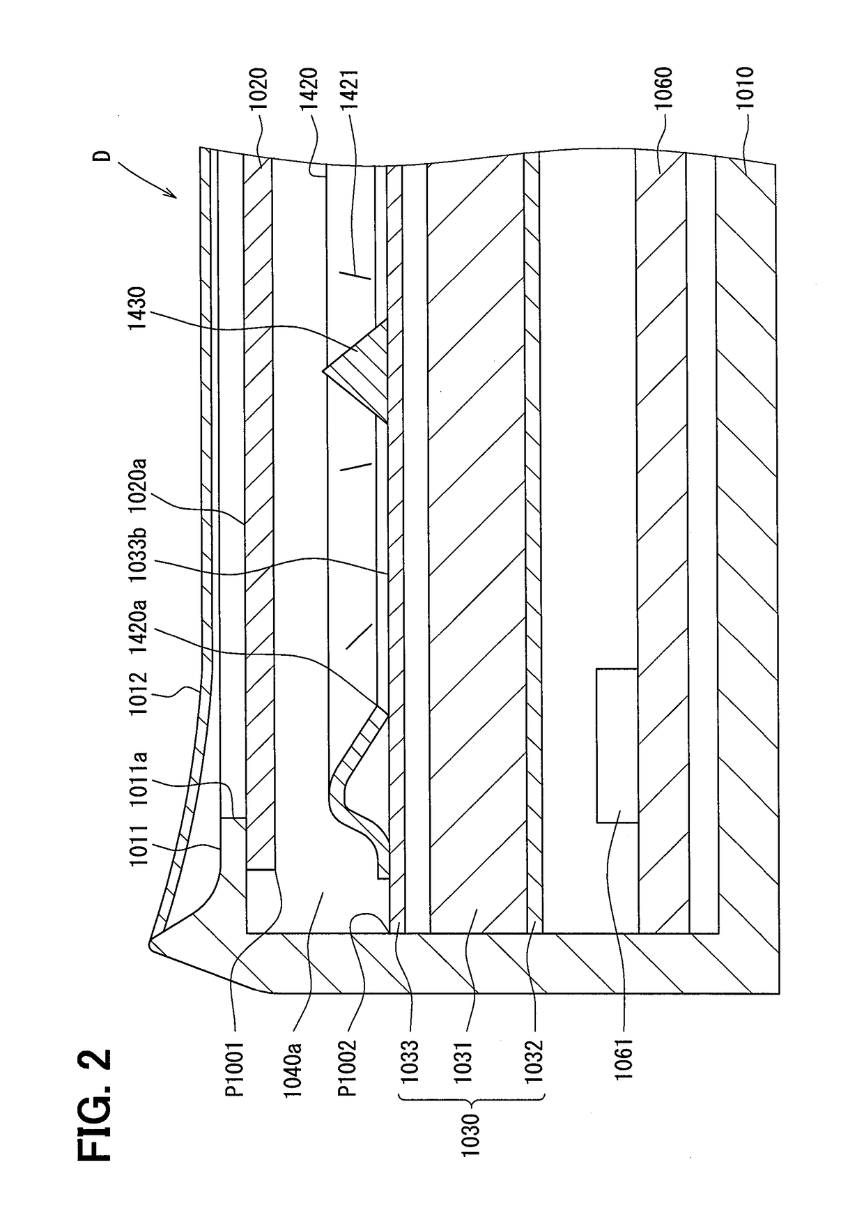
[0099]As illustrated in FIG. 2, the display device D is configured to be mainly provided with a case 1010, a liquid crystal panel 1020, a backlight 1030, a decorative ring 1420, a decorative boss member 1430, and a circuit board 1060. The liquid crystal panel 1020, the backlight 1030, the circuit board 1060, and the like are accommodated and held in the case 1010, which is a resinous case that has a light shielding property.

[0100]The liquid crystal panel 1020 is a TFT liquid crystal panel that is configured to have a liquid crystal layer in which a liquid cr...

second embodiment

[0140]In the present embodiment, real objects include a pointer 1040 and a wall member 1400 extending along an outer edge of a visible region of a display surface 1020a as illustrated in FIGS. 8 and 9. The outer edge of the visible region is identified by a wall surface of an opening portion 1011a of a facing plate 1011. The wall member 1400 has a tubular shape, extends in an annular shape along the outer edge, and is shaped such that its opening area increases in a direction toward a liquid crystal panel 1020. The pointer 1040 is positioned in the tubular shape of the wall member 1400. The wall member 1400 is a resinous member that has a light transmissive property.

[0141]The pointer 1040 has a pointer portion 1041 and a boss portion 1042.

[0142]The pointer portion 1041 and the boss portion 1042 are integrally formed of light transmissive resin. A rotating shaft 1051 is fixed to the boss portion 1042. The rotating shaft 1051 is placed to be inserted into through holes 1031a, 1032a, a...

third embodiment

[0145]In the present embodiment, a decorative plate 1440 is placed between a backlight 1030 (first backlight) and a liquid crystal panel 1020 as illustrated in FIG. 10. The decorative plate 1440 is a resinous plate that has a light transmissive property, and shade regions P1050 blocking light transmission are disposed in predetermined regions of the decorative plate 1440. Halftone dots in the drawing represent the shade regions P1050. The shade regions P1050 are provided by, for example, a non-light transmissive paint such as a black non-light transmissive paint being applied to the predetermined regions of the decorative plate 1440, and the parts to which the paint is not applied are corresponding to light transmissive regions P1050a, P1050b, P1051, and P1052.

[0146]The decorative plate 1440 is placed in parallel to the backlight 1030, and is subjected to transmitted illumination by the backlight 1030 once a light source 1034 is turned on. Then, the shapes of the light transmissive ...


PUM


Abstract

A display device includes a liquid crystal panel providing a display surface where an image is displayed, a backlight emitting light to the liquid crystal panel from behind, a real object placed between the liquid crystal panel and the backlight and visible through the liquid crystal panel, and a controller controlling the liquid crystal panel such that a specific pixel region of the display surface behind which the real object is positioned is higher in light transmittance than another pixel region of the display surface.

Description

CROSS REFERENCE TO RELATED APPLICATIONS[0001]This application is based on and incorporates herein by reference Japanese Patent Applications No. 2014-181584 filed on Sep. 5, 2014, No. 2014-181585 filed on Sep. 5, 2014, No. 2014-181586 filed on Sep. 5, 2014, No. 2014-181587 filed on Sep. 5, 2014, No. 2014-207414 filed on Oct. 8, 2014, No. 2014-245280 filed on Dec. 3, 2014, and No. 2015-045147 filed on Mar. 6, 2015.TECHNICAL FIELD[0002]The present disclosure relates to a display device including a liquid crystal panel.BACKGROUND ART[0003]In some display devices according to the related art, a displayed content is changed by movement of a real object such as a pointer to point at a scale. In the display devices disclosed in Patent Documents 1 and 2, in contrast, various changes in displayed content are realized with ease by an image imitating the real object being displayed on a liquid crystal panel.[0004]The liquid crystal panel entails physical limitations in terms of the three-dimens...

Claims


Application Information

Patent Timeline
IPC IPC(8): B60Q3/14G09G3/36
CPCB60Q3/14G09G3/36G09F9/35B60K37/02G01D11/28G01D7/002B60K35/00G02F1/133B60K2370/1531B60K2370/154B60K2370/155B60K2370/1868B60K2370/20B60K2370/23B60K2370/31B60K2370/332B60K2370/334B60K2370/336B60K2370/341B60K2370/347B60K2370/52B60K2370/682B60K2370/695B60K2370/698G01D7/06G02F1/1336G02F2201/44G09G3/003G09G3/3406G09G3/3611G09G2320/0686G02F1/133374G01D7/00G09G3/34
Inventor TANE, SEIGOFUJITA, KATSUMI
Owner DENSO CORP
Why Eureka
Try Eureka