
Wall Construction

a technology for building walls and walls, applied in the direction of walls, constructions, coverings/linings, etc., can solve the problems of prone to corrosion of lower plates b>116/b>, accumulated moisture in use, etc., and achieve the effect of reducing the incidence of corrosion and eliminating the tendency of walls

Active Publication Date: 2017-09-07
DESIGNSTONE LLC
View PDF5 Cites 2 Cited by
  • Summary
  • Abstract
  • Description
  • Claims
  • Application Information

AI Technical Summary

Benefits of technology

The patent describes a device that helps prevent water from accumulating at the bottom of a wall and causing corrosion. This is achieved by using a bottom plate with a drainage channel that allows water to flow out of the lower part of the wall. This reduced the incidence of corrosion at the bottom of the wall and improved the overall quality of the construction.

Problems solved by technology

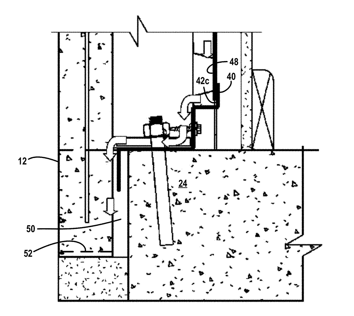
Although the wall construction shown in FIG. 6 has worked well, on occasion it has been found that the lower plate 116 has a tendency to accumulate moisture in use.
Thus, it has been found that the lower plate 116 is prone to corrosion.

Method used


Image

  • Wall Construction
  • Wall Construction
  • Wall Construction

Examples


Embodiment Construction

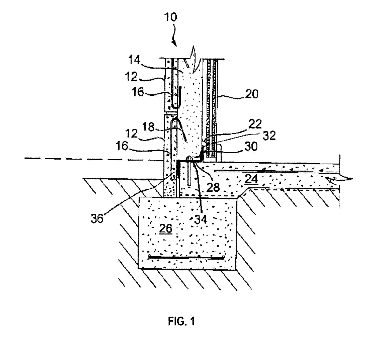
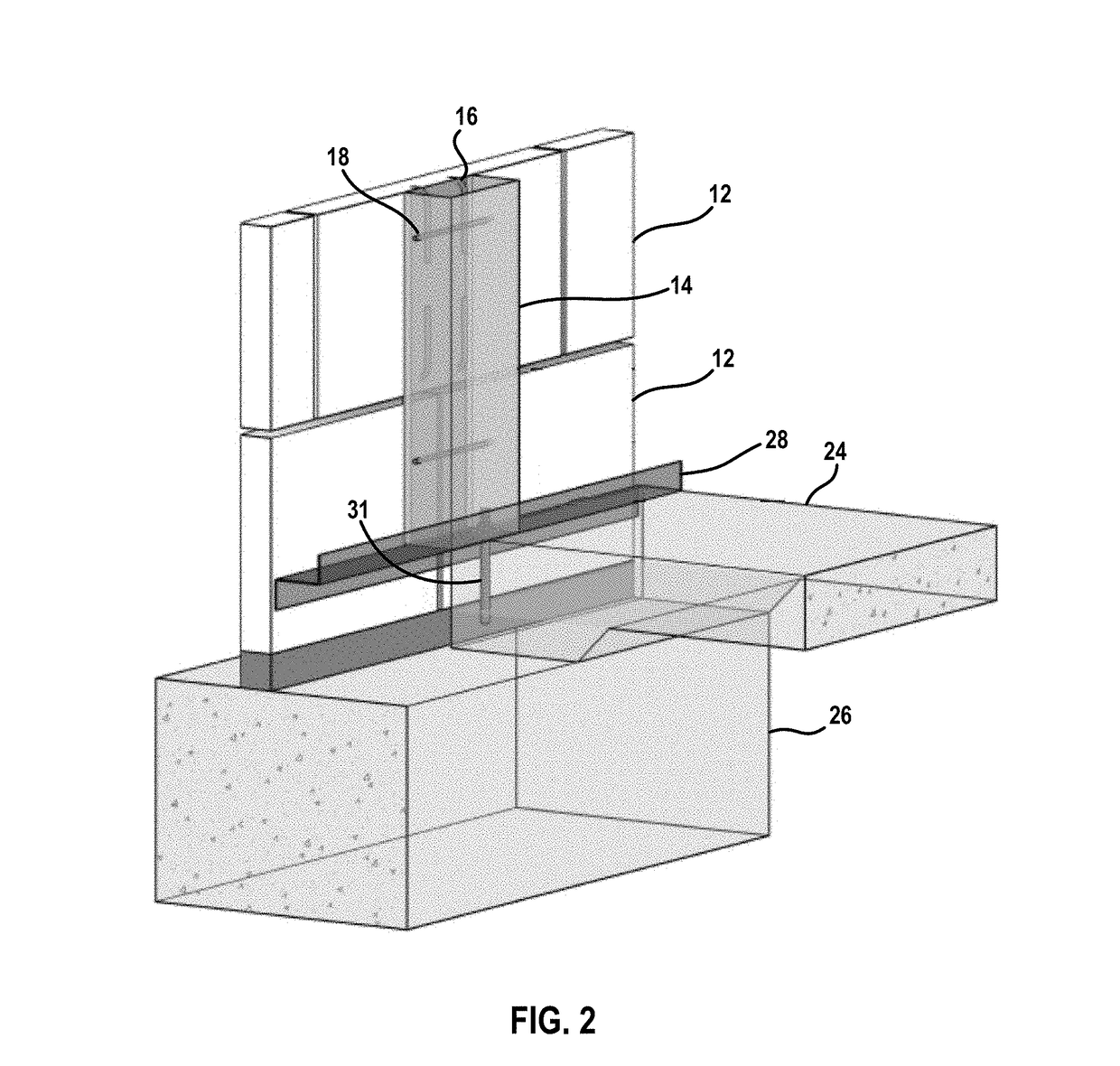
[0020]FIGS. 1 and 2 illustrate a wall construction 10 having a number of concrete panels 12 mounted on a number of channel-shaped steel studs 14. The studs 14 are spaced apart from one another along the length of the wall construction. Each panel 12 has a rearwardly and downwardly extending tie member 16. The tie members 16 are incorporated into the structure of the concrete panels 12 and extend outwardly and rearwardly into the studs 14. The studs 14 are oriented so that the channels thereof face the concrete panels.

[0021]Further, in the studs 14 the tie members 16 engage with respective pin members 18 each of which extends laterally across the channel of a respective stud 14. In use, the studs 14 are filled with concrete after the panels 12 and the tie members 16 are in place.

[0022]Still further, the construction 10 includes a furring channel 20 which is disposed inwardly of a stud 14. The furring channel 20 is spaced apart from the stud 14 by one or more generally U shaped bracke...


PUM


Abstract

A wall construction has a number of spaced upright channel-shaped studs and a number of concrete panels that form an exterior wall. The lower end of the studs are mounted on a concrete foundation member, and are provided with respective lower plates that enable moisture to drain away from the from the lower ends of the studs.

Description

RELATED APPLICATION[0001]This application claims priority from co-pending Australian Provisional Patent Application No. 2016900779 “A Wall Construction” filed Mar. 2, 2016 at Attorney Docket No. P8040AU00, with inventor David Allan Burke and applicant Designstone Pty Ltd, which priority application is incorporated by reference as if fully set forth herein.FIELD OF THE DISCLOSURE[0002]The disclosure relates generally to a wall construction for buildings.BACKGROUND OF THE DISCLOSURE[0003]Australian Patent Number 641920 incorporated by reference as if fully set forth herein discloses a wall construction shown in FIG. 6 that includes a number of spaced apart, uptight channel-shaped studs 118 and a number of concrete panels 126.[0004]The studs 118 are supported on a concrete footing and slab 110 formed as a one piece unit in situ. The slab 110 is reinforced by mesh reinforcement 112 and has a peripheral recess 114 arranged to receive lower ends of the concrete panels 126.[0005]Each concr...

Claims


Application Information

Patent Timeline
Patent Type & Authority Applications(United States)
IPC IPC(8): E04B2/60E04F13/14E04B1/64E04B1/62
CPCE04B2/60E04B1/625E04B2103/06E04B1/642E04F13/141E04B1/7046E04B2001/2478E04B2001/2481
Inventor BURKE, DAVID ALLAN
Owner DESIGNSTONE LLC
Learn More