Pipe clamp

a technology of pipe clamps and handles, applied in the field of pipe clamps, can solve the problems of low clearance, ineffective user point of view, and easy tipping and achieve the effect of wide foot, effective use of the handle, and elimination of the tendency of the top heavy clamp to tipping over

Inactive Publication Date: 2009-02-10
ROCKLER
View PDF18 Cites 9 Cited by
  • Summary
  • Abstract
  • Description
  • Claims
  • Application Information

AI Technical Summary

Benefits of technology

[0010]A principle object and advantage of the present invention is that it has a taller foot that raises the pipe 1½″ above the bench. This also increases the clearance between the handle and the bench top to 1¼″, enough to effectively use the handle while the clamp is positioned anywhere on the bench top.
[0011]A second principle object and advantage of the present invention is that it has a wider foot that eliminates the tendency of the top heavy clamp from tipping over. The new wide foot is also relieved in the center so that it rests on two pads at the end of the foot, allowing it to provide a stable base even on uneven surfaces.
[0012]Another principle object and advantage of the present invention is that it has holes drilled in both the front and back clamping faces. This facilitates adding clamping cauls and specialty fixtures to the clamp for special clamping applications. Cauls are used to spread the clamping force over a wider surface than simply the 1⅞″ wide clamp face. Jigs are used to clamp specific projects that may have unusual shapes that are difficult, if not impossible to clamp with a standard pipe clamp. Examples would be clamping concave or convex shapes.
[0013]Another principle object and advantage of the present invention is that it has a “hook” on the foot of the head section. This “hook” hangs over the shelf or rack, and prevents the clamp from falling off. It also eliminates having to move the tail section or tightening the clamp on the shelf. This allows quick mounting and dismounting, and provides a secure method store the pipe clamp.

Problems solved by technology

All pipe clamps on the market are designed with a narrow “foot” This is an effective design for molding the part, but is ineffective from a user point of view.
The problem is that it is inherently top heavy and unstable, causing the clamp to tip over with little effort.
This is a problem during use when the user is positioning the pieces of wood that are to be glued and clamped.
This low clearance is a problem because it only allows a ⅜″-½″ clearance between the handle and the bench top.
This is not enough clearance to effectively grip the handle during use.

Method used


Image

  • Pipe clamp
  • Pipe clamp
  • Pipe clamp

Examples


Embodiment Construction

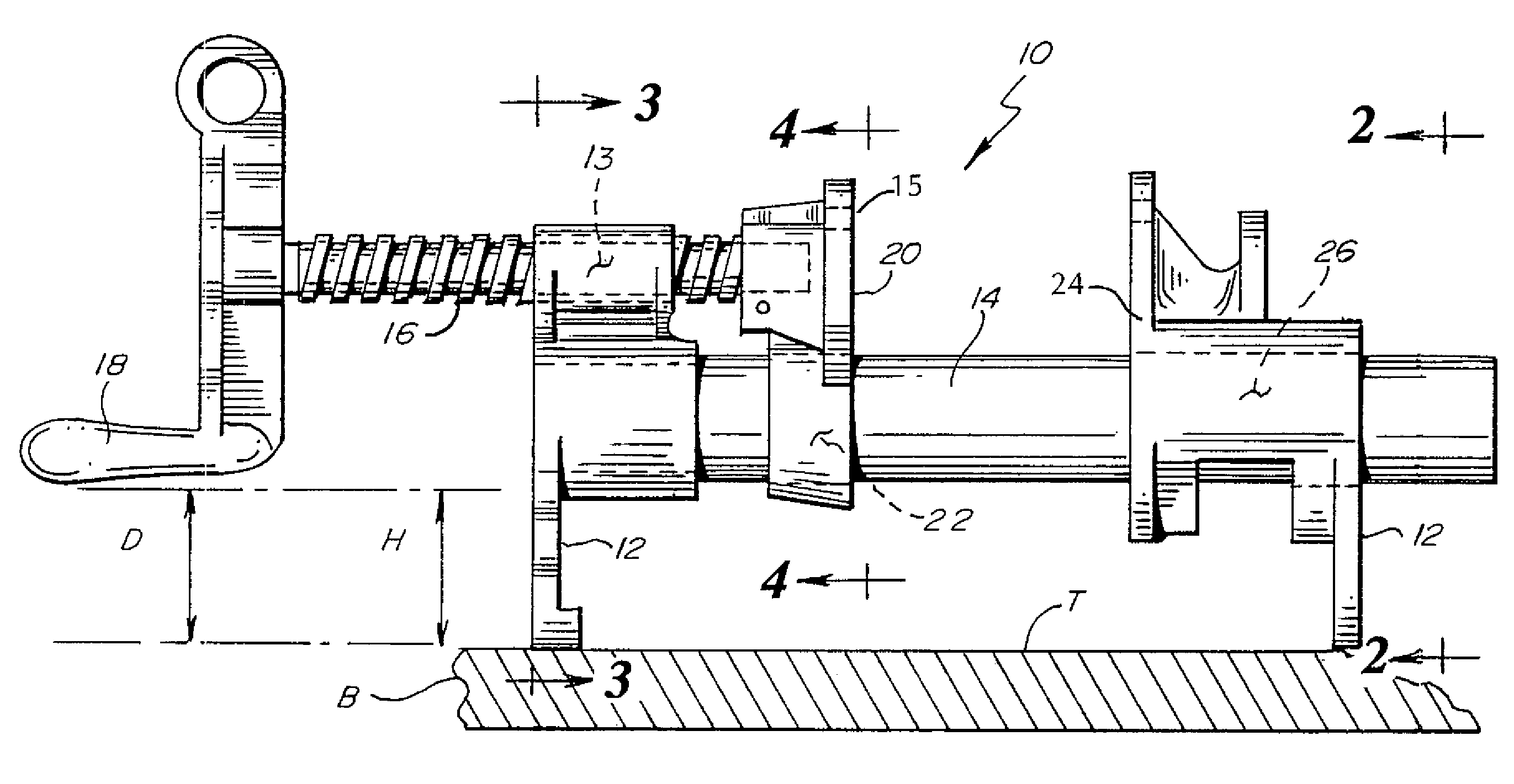
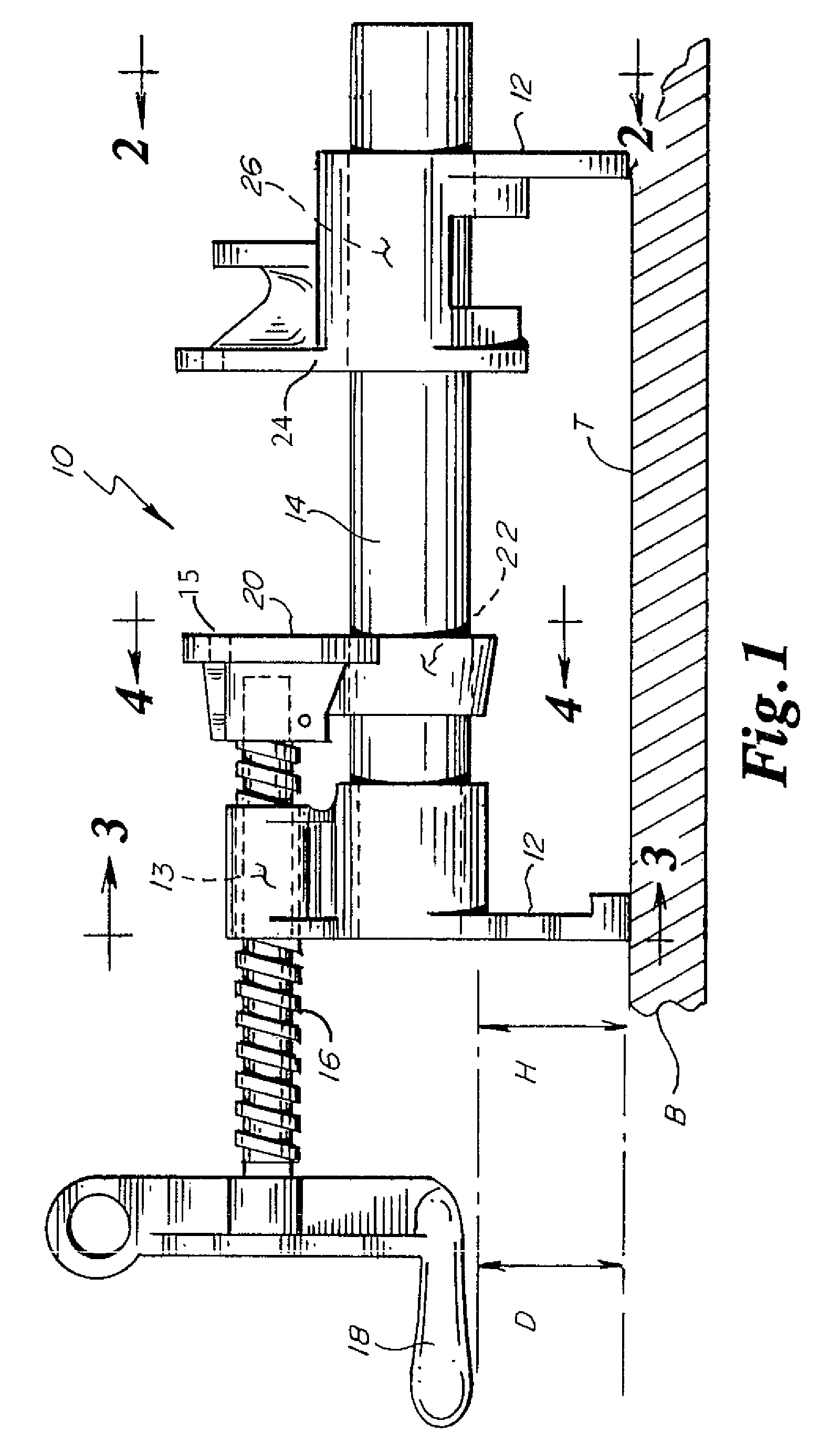
[0020]The pipe clamp of the present invention is generally shown in the Figures as reference numeral 10.

[0021]As best seen in FIG. 1, the pipe clamp 10 comprises a pair of supports 12 supporting an elongated body 14. The apparatus 10 further comprises a clamping member 15. A screw 16 is threadably engaged in a threaded aperture 13 and terminates in the clamping member 15. A handle 18 is attached to the screw 16. The handle is used to drive the screw 16 into and out of the threaded aperture 13. A second aperture 22 engages the elongated body 14.

[0022]The clamping member 15 terminates in a first clamping face 20.

[0023]The other support 12 has a second clamping face 24, which has a third aperture 26 therethrough engaging the elongate body 14.

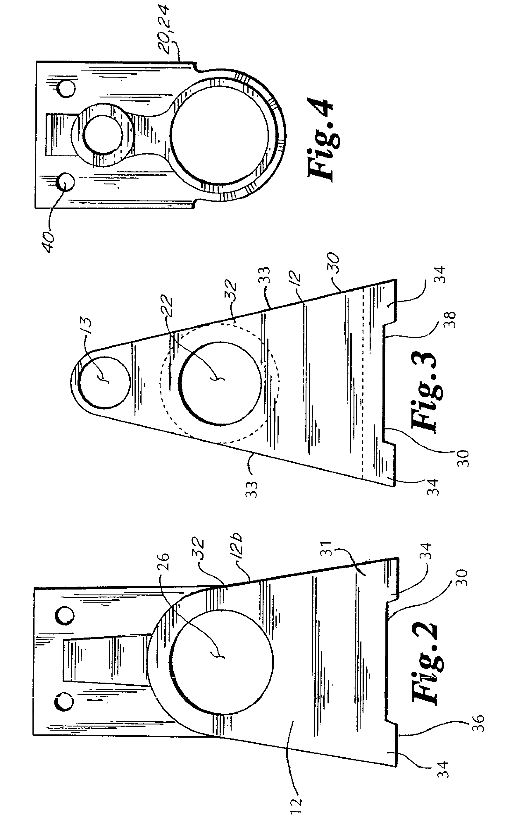
[0024]As best seen in FIGS. 2 and 3, the supports 12, have a broad base 30. The base 30 has a first portion 31 which is substantially broader than the second portion 32 enclosing the apertures 22, 26. This results in the pipe clamp 10 being very st...


PUM


Abstract

A pipe clamp for clamping objects has wide, stable feet that prevent the clamp from tipping over. The feet are of such a height that the clamp handle can be rotated by the user without interference from the bench on which the pipe clamp rests. The clamping faces have holes drilled through them to allow jigs or cauls to be attached to the clamping faces to clamp unusually shaped objects. The clamp also has a hook on the foot for convenient hanging of the clamp for storage.

Description

[0001]This application claims priority to provisional application Ser. No. 60 / 408,115, filed Sep. 4, 2002, entitled PIPE CLAMP.BACKGROUND OF THE INVENTION[0002]The new pipe clamp of the present invention solves two common problems associated with pipe clamps.[0003]Common Problem #1. All pipe clamps on the market are designed with a narrow “foot” This is an effective design for molding the part, but is ineffective from a user point of view. The problem is that it is inherently top heavy and unstable, causing the clamp to tip over with little effort. This is a problem during use when the user is positioning the pieces of wood that are to be glued and clamped. Typically, two or more pipe clamps would be used to edge glue several pieces of wood together. The user applies glue to the edge of the pieces and positions them on the pipe clamps. Before the clamps are tightened, the pieces are typically adjusted side to side so the ends line up, and / or so the grain patterns are aligned correct...

Claims


Application Information

Patent Timeline
Patent Type & Authority Patents(United States)
IPC IPC(8): A47B96/06B23Q3/02B25B1/02B25B1/10B25B1/20B25B5/00B25B5/10B25B5/16
CPCB25B1/103B25B5/006B25B5/102B25B5/163
Inventor KROHMER, STEVEN D.
Owner ROCKLER
Why Eureka
Try Eureka