Hair removal apparatus

a hair removal and hand-held technology, applied in the field of hair removal, can solve the problems of unpleasant pain and still be experienced, and achieve the effect of increasing user friendliness and facilitating hair removal

Active Publication Date: 2017-09-14
KONINKLJIJKE PHILIPS NV
View PDF6 Cites 1 Cited by
  • Summary
  • Abstract
  • Description
  • Claims
  • Application Information

AI Technical Summary

Benefits of technology

[0003]There may thus be a need to further facilitate hair removal and increase user friendliness.

Problems solved by technology

However, epilating can be a procedure in which a user may experience pain.
However, it has been shown that during hair removal, pain may still be experienced to a rather unpleasant degree.

Method used


Image

  • Hair removal apparatus
  • Hair removal apparatus
  • Hair removal apparatus

Examples


Embodiment Construction

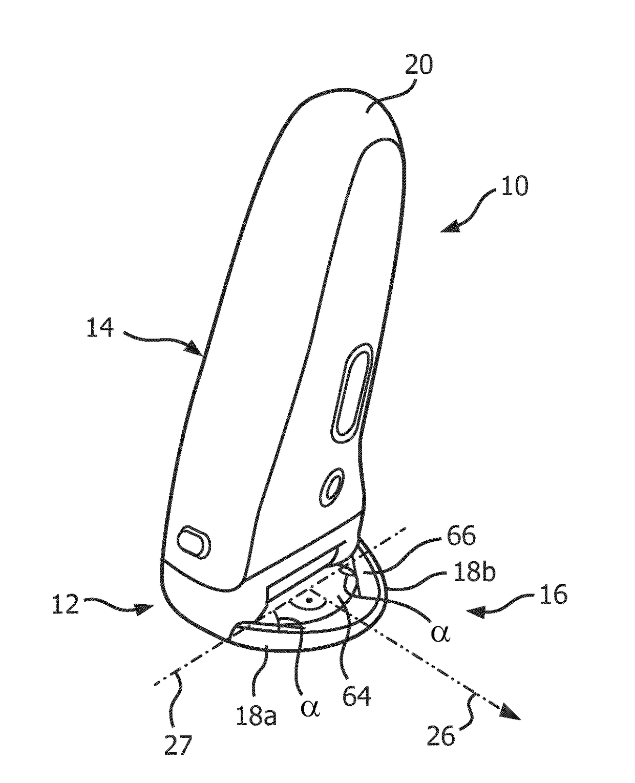
[0040]FIG. 1 shows a handheld hair removal apparatus 10 that comprises a hair removal arrangement 12 (further shown in FIGS. 3 and 4), a support structure 14 (not further shown in detail) for supporting the hair removal arrangement and a skin stretching device 16 that is attached to the support structure 14 and that comprises at least two leading surface portions 18a and 18b. In FIG. 1, the hair removal apparatus 10 is shown in a standing position on a surface, similar to an arrangement during operation.

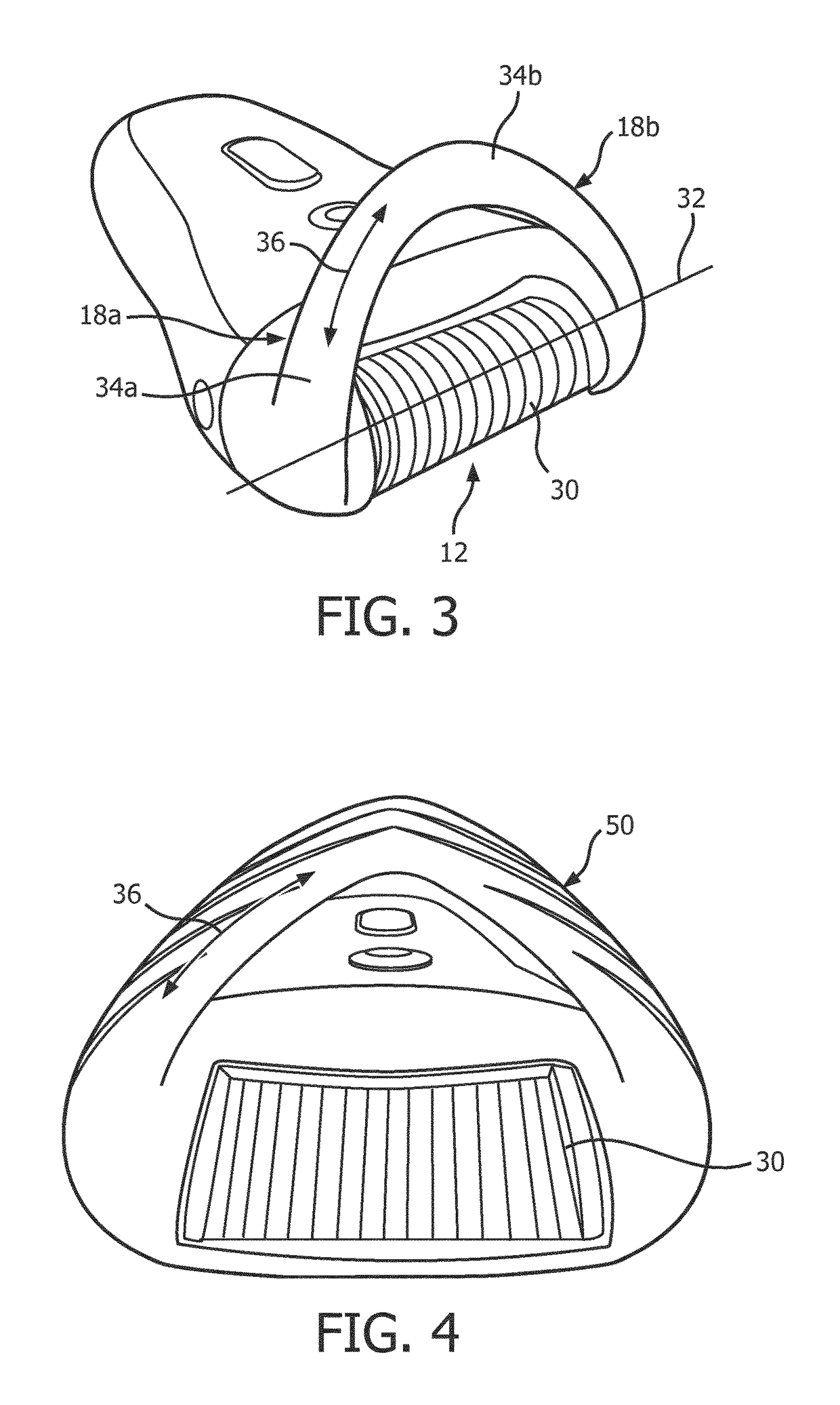
[0041]Referring to FIG. 3, the hair removal arrangement 12 comprises a skin contact portion 30 for contacting a user's skin during operation. The skin contact portion 30 extends at least along a primary axis 32 extending perpendicularly to a main movement direction 26 (shown in FIG. 1) in which the apparatus 10 is to be moved relative to skin during use. It is noted that the primary axis 32 is perpendicular to the plane of the drawing of FIG. 7, i.e. perpendicular to the plane of pap...


PUM


Abstract

The present invention relates to hair removal, and in particular to a handheld hair removal apparatus. In order to reduce pain during hair removal, the handheld hair removal apparatus (10) comprises a hair removal arrangement (12), a support structure (14) and a skin stretching device (16) attached to the support structure and comprising at least two leading surface portions (18a, 18b) for skin contacting and stretching. The apparatus has a main movement direction (26) in which the apparatus is to be moved relative to skin during use. The hair removal arrangement comprises a skin contact portion (30) for contacting a user's skin during operation, wherein the skin contact portion extends at least along a primary axis (32) extending perpendicularly to the main movement direction (26). The at least two leading surface portions, seen in an imaginary plane comprising a base line (27) and extending parallel to the main movement direction (26), are arranged at opposite inclinations of at least 20° with respect to the base line (27), which extends perpendicularly to the main movement direction and parallel to the primary axis, and are each provided with a skin touching surface portion (34a, 34b) having a main direction of extension that is inclined a tan angle of at least 20° with the base line seen in said imaginary plane. During operation, the leading surface portions are brought into contact with the skin to act on the skin with a pushing force (42) having a first vector (38), parallel to the skin's surface, in a first direction (Y) parallel to the main movement direction, and a second vector (40), parallel to the skin's surface, in a second direction (X) perpendicular to the main movement direction. In an operational position, the skin stretching device is arranged in front of the skin contact portion with respect to the main movement direction. During operation, the skin stretching device provides a stretched skin portion between the at least two leading surface portions.

Description

FIELD OF THE INVENTION[0001]The present invention relates to hair removal, and in particular to a handheld hair removal apparatus.BACKGROUND OF THE INVENTION[0002]It is known to remove hair on body surfaces like skin portions of the arms or legs, for example. For such hair removal, handheld, motor-driven devices are used. For example, motor-driven epilators or shavers are widely used. However, epilating can be a procedure in which a user may experience pain. In WO 2009 / 150607 A2, a stimulation to the skin immediately before hairs are extracted from the skin (or after the removal of hair) is provided in the form of an epilator having a massage roller. The massage roller comprises pairs of elementary massaging members positioned in a V-shape relative to each other. As a further example, WO 2009 / 104124 A2 describes an epilator with interchangeable caps, which are coupled to a driving means of the epilator for vibrating, such that a user of the epilator experiences a vibration on the sk...

Claims


Application Information

Patent Timeline
Patent Type & Authority Applications(United States)
IPC IPC(8): A45D26/00B26B19/42
CPCA45D26/0028B26B19/42A45D26/0061A45D26/00
Inventor STEEMAN, JONNEKINDERMANN, SEBASTIAN ALEXANDERVAN ES, MICHELCORNELISSEN, MARJAN WILLEKE ESTHERKROP, NIENKE
Owner KONINKLJIJKE PHILIPS NV
Why Eureka
Try Eureka