
Aircraft Aerodynamic Surface With A Detachable Leading Edge

a leading edge and aerodynamic surface technology, applied in the direction of airflow influencers, spars/stringers, transportation and packaging, etc., can solve the problems of long time for interchanging and/or repairing the collided pieces, affecting the integrity of birds, and requiring secured, complicated attachment to the aircraft, so as to simplify the reparability and maintainability tasks. , the effect of reducing the cos

Inactive Publication Date: 2017-09-14
AIRBUS OPERATIONS SL
View PDF0 Cites 10 Cited by
  • Summary
  • Abstract
  • Description
  • Claims
  • Application Information

AI Technical Summary

Benefits of technology

The patent aims to make it easier to repair and maintain aircraft surfaces that have been hit by birds. It also aims to reduce the cost of these collisions.

Problems solved by technology

Bird-plane collisions during flight, take-off and landing happen every day, jeopardizing people and aircraft integrity.
This integration of these both functionalities results in a secured, but complicated attachment to the aircraft.
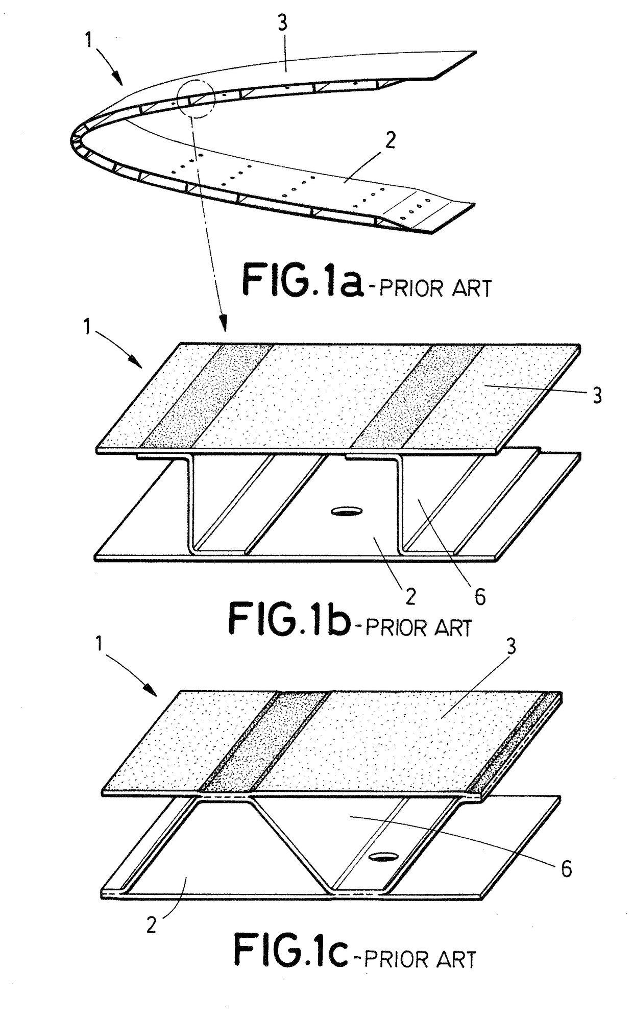
According to this, bird collisions demands long time for interchanging and / or repairing the collided pieces.

Method used


Image

  • Aircraft Aerodynamic Surface With A Detachable Leading Edge
  • Aircraft Aerodynamic Surface With A Detachable Leading Edge
  • Aircraft Aerodynamic Surface With A Detachable Leading Edge

Examples


Embodiment Construction

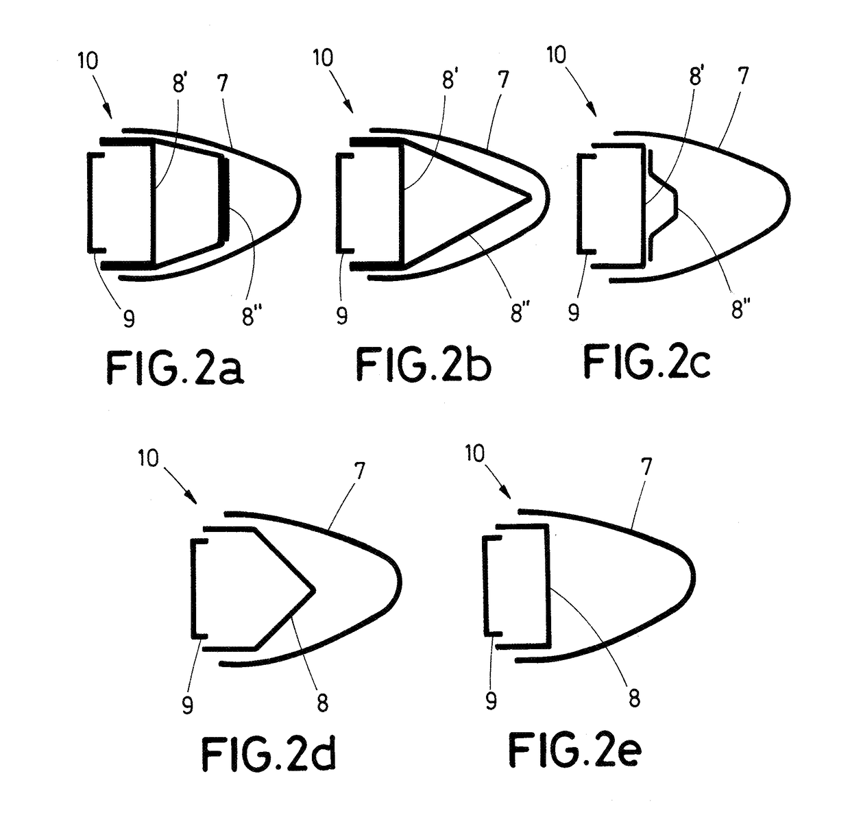
[0035]FIGS. 2a-2e show different embodiments of the aircraft aerodynamic surface of the invention.

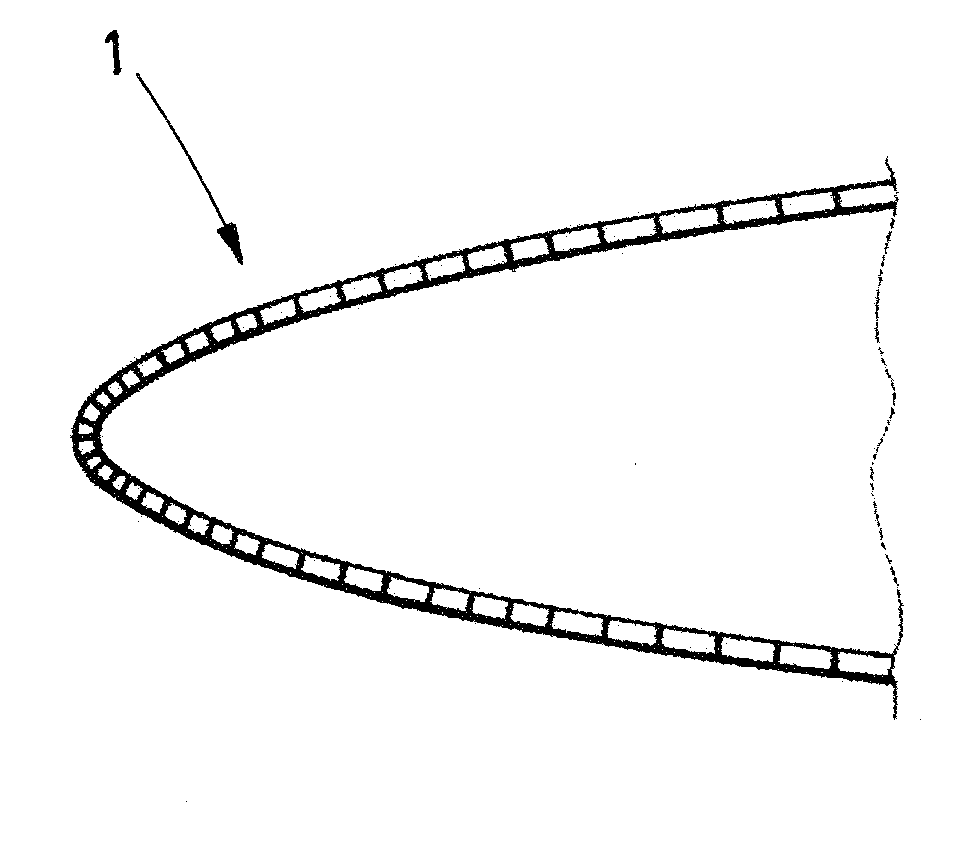
[0036]Conventionally, the aircraft aerodynamic surface 10 comprises an upper skin 11, a lower skin 12, and a front spar 9. According to the invention, the aircraft aerodynamic surface 10 comprises a leading edge 1 formed by an external shell 7 and an impact resisting structure 8, wherein at least one of the external shell 7 and the impact resisting structure 8 is fitted with the upper and lower skins 11, 12 of the torsion box.

[0037]The impact resisting structure 8 is spanwise arranged between the external shell 7 and the front spar 9 of the torsion box, and is configured for absorbing a bird strike to prevent damage in the front spar 9 and withstand aerodynamic load.

[0038]FIGS. 2a, 2b and 2c show an aircraft aerodynamic surface 10 comprising an impact resisting structure 8 formed by a rear piece 8′ and a front piece 8″. The rear piece 8′ is positioned near the front spar 9, and the fron...


PUM


Abstract

An aircraft aerodynamic surface includes a torsion box having an upper skin, a lower skin, and a front spar, and a leading edge having an external shell and an impact resisting structure. The external shell may be shaped with an aerodynamic leading edge profile, being configured to provide Laminar Flow Control (LFC) to the leading edge. The impact resisting structure is spanwise arranged between the external shell and the front spar, and is configured for absorbing a bird strike to prevent damage in the front spar. Also, at least one of the external shell and the impact resisting structure is fitted with the upper and lower skins of the torsion box to thereby facilitate leading edge exchange.

Description

FIELD OF THE INVENTION[0001]The present invention refers to an aircraft aerodynamic surface with a detachable leading edge configuration so as to provide an aerodynamic surface with dissociated functionalities.[0002]An aspect of the present invention may provide an aerodynamic surface for an aircraft with dedicated and improved components for its aerodynamic and structural functionalities.[0003]Another aspect of the present invention may provide an aerodynamic surface for an aircraft that is easily interchangeable to facilitate the maintainability and reparability of the same.[0004]Another aspect of the present invention may provide an aerodynamic surface for an aircraft that minimizes the cost and damage in a bird strike event.BACKGROUND OF THE INVENTION[0005]Bird-plane collisions during flight, take-off and landing happen every day, jeopardizing people and aircraft integrity.[0006]Certification regulations governing certain categories of aircraft require that, in the event of dama...

Claims


Application Information

Patent Timeline
IPC IPC(8): B64C3/26B64C5/02B64C3/18
CPCB64C3/26B64C5/02B64C3/185B64D2045/0095B64C3/28B64C21/06Y02T50/10
Inventor CEBOLLA GARROFE, PABLOVELEZ DE MENDIZABAL ALONSO, IKERCRESPO PENA, SOLEDADCALERO CASANOVA, LVAROGARCIA NIETO, CARLOSGUINALDO, ENRIQUEHONORATO RUIZ, FRANCISCO JAVIERTORRES SALAS, LVARO
Owner AIRBUS OPERATIONS SL
Learn More