Lifting device

Inactive Publication Date: 2017-09-14
SYNCMOLD ENTERPRISE CORP
View PDF2 Cites 3 Cited by
  • Summary
  • Abstract
  • Description
  • Claims
  • Application Information

AI Technical Summary

Benefits of technology

The invention offers a lifting device with a simple, small, and slim design that meets the needs of users for a simple structure. The device provides adequate support for the display and has lifting functions. This makes it easy to handle and use the display on a daily basis.

Problems solved by technology

Therefore, it is difficult to meet the desire of slim appearance.

Method used


Image

  • Lifting device
  • Lifting device
  • Lifting device

Examples


embodiment 1

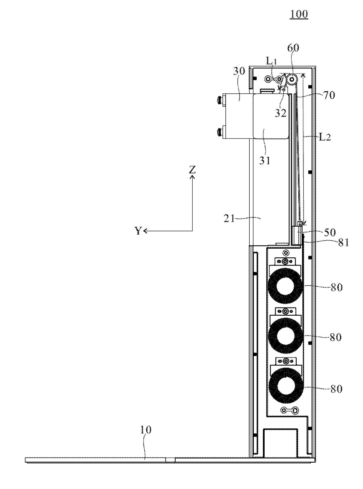
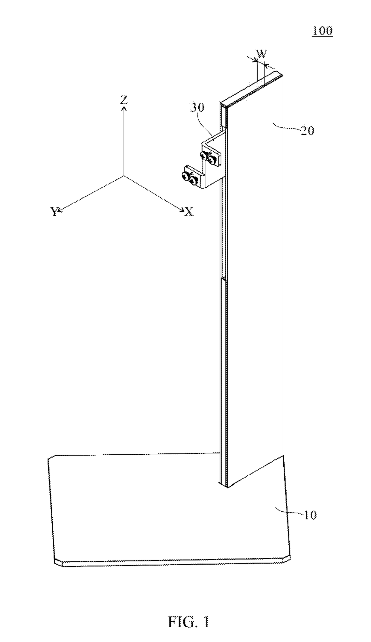
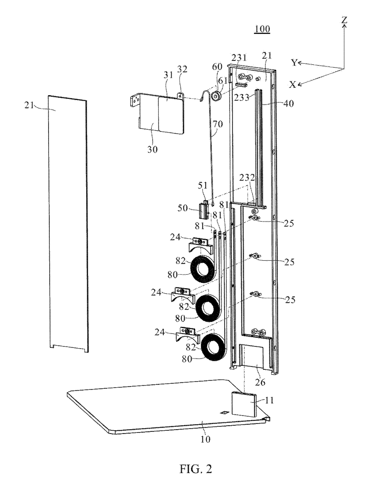
[0024]Please refer to FIG. 1 and FIG. 2, FIG. 1 is a perspective view of the lifting device of a preferred embodiment of the present invention, and FIG. 2 is an explosion view of the lifting device of a preferred embodiment of the present invention. The illustrated lifting device 100 is utilized to carry a display on a working surface and mainly comprises a base 10, a frame 20, a loading slider 30, a slide rail 40, a sliding member 50, a pulley 60, a rope 70, and three constant force springs 80.

[0025]The frame 20 is disposed on the base 10, wherein the base 10 has an engaging protrusion 11 engaging to an engaging notch 26 of the frame 20. The frame 20 includes two opposite side plates 21 perpendicularly disposed on the base 10. The loading slider 30, the slide rail 40, the sliding member 50, the pulley 60, the rope 70, and the constant force springs 80 are received between the side plates 21.

[0026]As illustrated in FIG. 1 and FIG. 2, the axial direction of the constant force springs...


PUM


Abstract

A lifting device for holding a display is provided. The lifting device has a slim appearance, wherein a width of a frame of the lifting device is 5-30 mm. The lifting device holds the display on a working surface through a plurality of constant force springs.

Description

CROSS REFERENCE TO RELATED APPLICATION[0001]This application claims the benefits of the U.S. Provisional Application Ser. No. 62 / 305,091, filed on Mar. 8, 2016. The entirety of said Provisional Application is incorporated herein by reference.BACKGROUND OF THE INVENTION[0002]1. Field of the Invention[0003]The present invention relates to a lifting device, and more particularly, to a lifting device with an ultra-slim appearance.[0004]2. Description of Related Art[0005]A lifting device as disclosed in Taiwan Utility Patent No. M482023 is composed of a supporting frame, a limiting base, a bearing base, a plurality of fixing parts, a plurality of constant force parts, a slider, and a sliding slot. The lifting device occupies a large width laterally because the constant force parts are disposed side by side with rails disposed at both sides of the constant force parts. Therefore, it is difficult to meet the desire of slim appearance.[0006]Therefore, the present invention provides a novel ...

Claims


Application Information

Patent Timeline
IPC IPC(8): F16M11/04F16M11/22
CPCF16M11/046F16M2200/047F16M2200/08F16M11/22
Inventor LEE, YUAN-CHILEE, KO-HSIEN
Owner SYNCMOLD ENTERPRISE CORP
Why Eureka
Try Eureka