Wheel-type fan driving method and wheel-type fan

A driving method and fan technology, applied in non-variable-capacity pumps, machines/engines, pump devices, etc., can solve the problems of single appearance, influence, outdated technology, etc., and achieve the effect of high energy efficiency ratio

Inactive Publication Date: 2012-08-15
徐荻明
View PDF6 Cites 2 Cited by
  • Summary
  • Abstract
  • Description
  • Claims
  • Application Information

AI Technical Summary

Problems solved by technology

Although people pursue personalization in terms of appearance and function through various methods, due to the relatively old technology in this industry and the fixed and single appearance, several traditional types of electric fans, such as standing fans, rotary fans, table fans, and wall fans, are common in the market. Fans, their similarity in appearance and function is very serious, which seriously affects and restricts the development and improvement of electric fans

Method used


Image

  • Wheel-type fan driving method and wheel-type fan
  • Wheel-type fan driving method and wheel-type fan
  • Wheel-type fan driving method and wheel-type fan

Examples


Embodiment 1

[0065] A method for driving a wheeled fan,

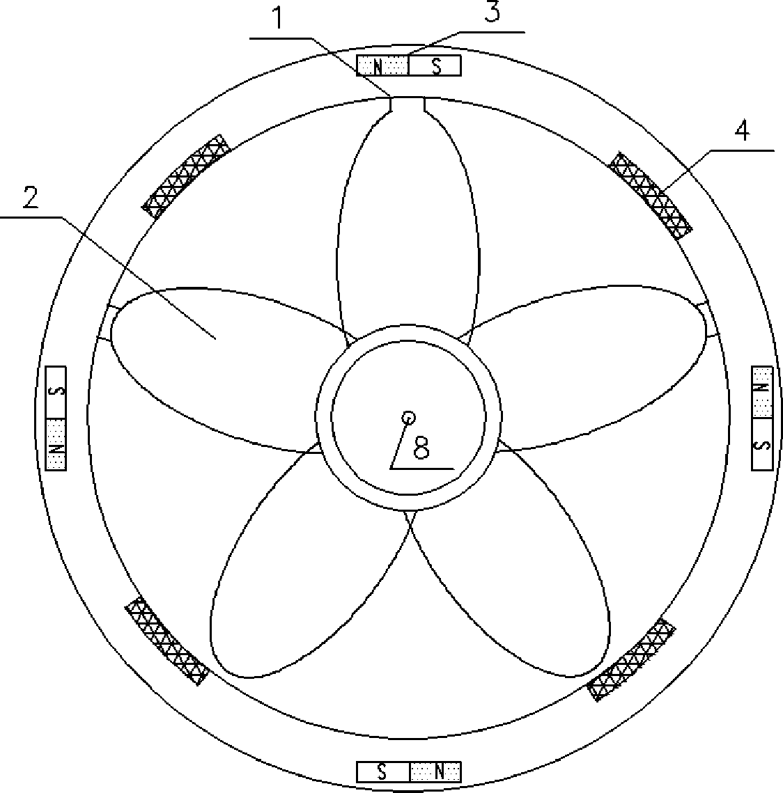
[0066] Step 1 Take a ring 1, connect the impeller 2 composed of blades to the ring 1, embed 4~8 permanent magnet blocks 3 on the ring 1 and distribute 4~8 permanent magnet blocks 3 along the circumferential direction, Set the reflective area 4 on the ring 1;

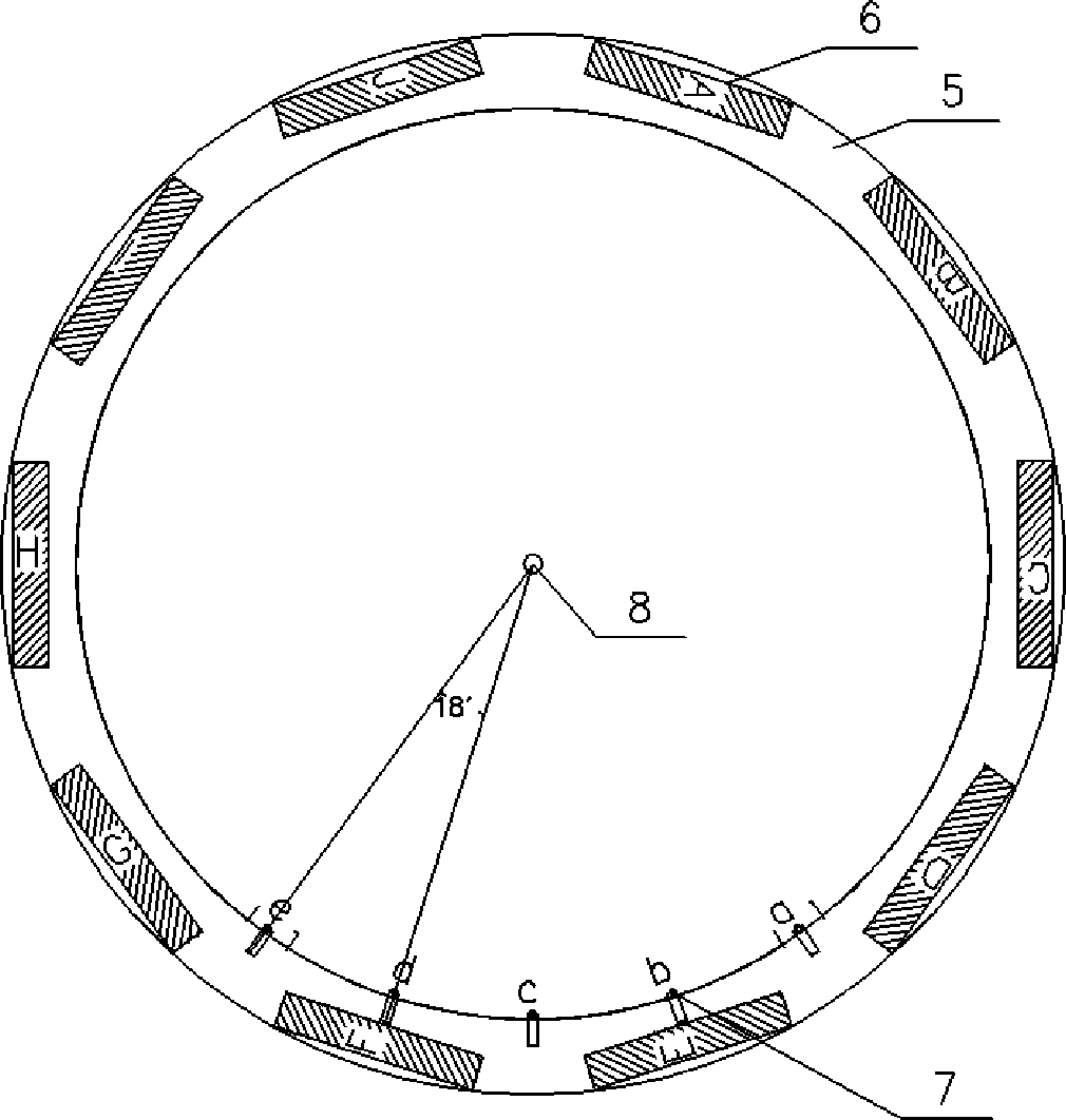
[0067] Step 2 Take a board and use the said board as the machine base 5, set 3~10 groups of electromagnetic coil groups 6 arranged along the circumference on the machine base 5 and photoelectric switches 7 whose number is the number of electromagnetic coil groups. The switch 7 respectively forms a series circuit with each group of electromagnetic coil groups;

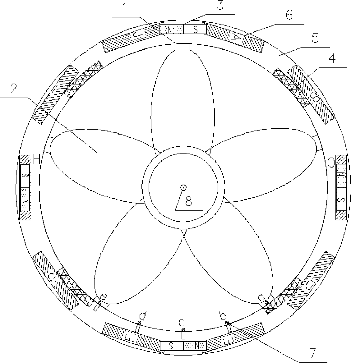
[0068] Step 3: Set a rotating shaft 8, through which the circular ring 1 and the base 5 form a rotational connection, and make the surface of the circular ring 1 with the permanent magnet block 3 and the base 5 with the electromagnetic coil and the photoelectric switch 7 faces face to face;

[0069] Step 4 Power on e...

Embodiment 2

[0074] A wheeled fan, comprising a ring 1, an impeller 2, a machine base 5 and a rotating shaft 8, the impeller 2 is arranged in the ring 1, and 4 to 8 permanent magnet blocks 3 are embedded on the ring 1 and 4~ Eight permanent magnet blocks 3 are distributed along the circumferential direction, and a reflective area 4 is set on the ring 1; 3 to 10 sets of electromagnetic coils 6 arranged along the circumference and a number equal to the number of sets of electromagnetic coils are set on the base 5. Photoelectric switch 7, each photoelectric switch 7 is connected in series with each pair of electromagnetic coil groups respectively to form a series loop; Described impeller 2 forms rotational connection with support 5 by rotating shaft 8, is provided with the surface of the circular ring 1 of permanent magnet block 3 and sets The surfaces of the base 5 with the electromagnetic coil and the photoelectric switch 7 face each other; when each series circuit is powered on and the fan...


PUM


Abstract

The invention provides a wheel-type fan driving method and a wheel-type fan. The method comprises the following steps of: arranging a permanent magnet block and a light reflecting region on a ring provided with an impeller; arranging electromagnetic coil sets and an optoelectronic switch on a base, and connecting the optoelectronic switch with the electromagnetic coil sets in series; rotatably connecting the ring with the base by virtue of a rotating shaft; and starting up the fan, and switching on the optoelectronic switch meeting with the light reflecting region, so that the electromagnetic coils are electrified, and the fan is driven. The wheel-type fan comprises the ring, the impeller, the base and the rotating shaft, wherein the impeller is arranged in the ring, and the permanent magnet block and the light reflecting region are arranged on the ring; the electromagnetic coil sets and the optoelectronic switch are arranged on the base, and the optoelectronic switch is connected with each electromagnetic coil set in series; the impeller is rotatably connected with the base by virtue of the rotating shaft; and after each series loop is electrified and the fan is started up, the light reflecting region meets with the optoelectronic switch, the optoelectronic switch is switched on, and the electromagnetic coils on the corresponding series loops are electrified to drive the fan.

Description

technical field [0001] The invention relates to a driving method of a wheeled fan and the wheeled fan, belonging to the technical field of electrical engineering. Background technique [0002] The use of electric fans has a long history. Since the use of electric fans in 1830, electric fans have been unable to get rid of the heavy motor shape in the center of the blades. Although people pursue personalization in terms of appearance and function through various methods, due to the relatively old technology in this industry and the fixed and single appearance, several traditional types of electric fans, such as standing fans, rotary fans, table fans, and wall fans, are common in the market. Fans, the similarity of their appearance and function is very serious, which seriously affects and restricts the development and promotion of electric fans. The future development trend and direction of the electric fan industry require design to break through the tradition. Through active...

Claims


Application Information

Patent Timeline
Patent Type & Authority Applications(China)
IPC IPC(8): F04D25/08
Inventor 徐荻明
Owner 徐荻明
Why Eureka
Try Eureka