Control Methods and Apparatus for an Irrigation System Which Employs Pressure Pulse-Based Communications

Inactive Publication Date: 2017-09-21
RAINBOXX INC
View PDF0 Cites 0 Cited by
  • Summary
  • Abstract
  • Description
  • Claims
  • Application Information

AI Technical Summary

Benefits of technology

The present invention provides a control unit for a pressure pulse communication-based irrigation system that ensures the system is ready for transmitting control signals to the remote zone valves. The control unit includes a communication output terminal and a supply output terminal, and operates to apply a communication control signal to the communication signal circuit and a supply control signal to the supply signal circuit. The control unit also includes a controller that directs the supply control signal to the supply valve and the communication control signal to the communication signal circuit after a communication condition is met in the network of irrigation conduits. The invention allows for the efficient and effective operation of the irrigation system.

Problems solved by technology

First there is the added cost of the electrical wires and the cost of installing the wires.
Additionally, the wires are subject to damage during yard work.
The wires and connections to the wires are also subject to corrosion since they are exposed to a relatively harsh outdoor and underground environment.
Although this pressure pulse communication arrangement for controlling the zone valves in an irrigation system eliminates the need for electrical wires to the zone valves, the arrangement raises a number of other issues which have ultimately prevented the wide-spread adoption of such systems.

Method used


Image

  • Control Methods and Apparatus for an Irrigation System Which Employs Pressure Pulse-Based Communications
  • Control Methods and Apparatus for an Irrigation System Which Employs Pressure Pulse-Based Communications
  • Control Methods and Apparatus for an Irrigation System Which Employs Pressure Pulse-Based Communications

Examples


Embodiment Construction

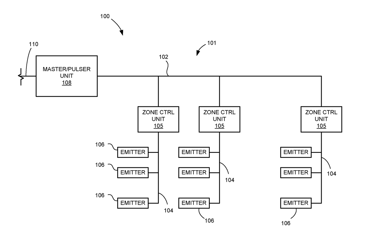
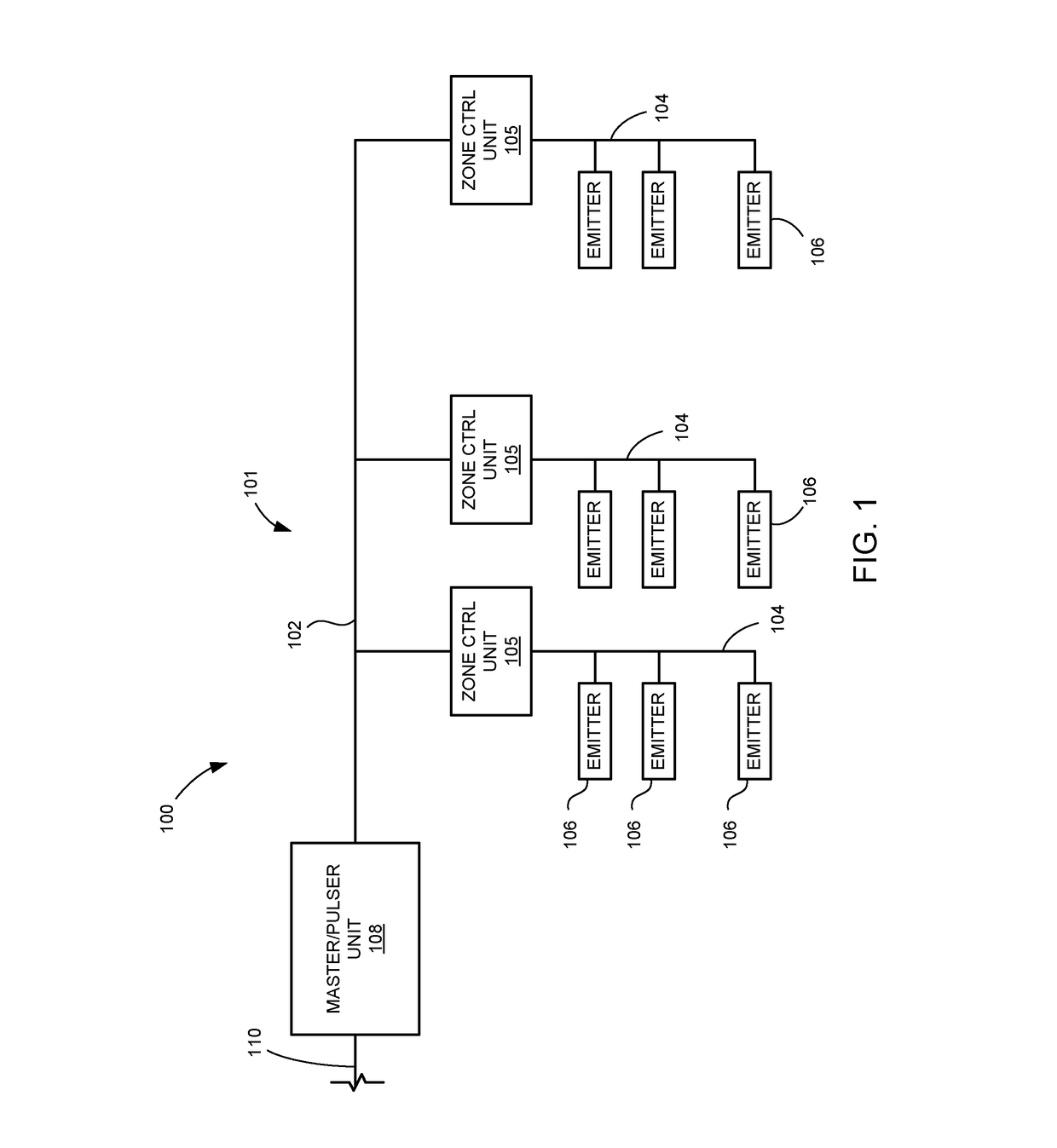
[0019]Referring to FIG. 1, an irrigation system 100 in which the present invention may be employed includes a network 101 of irrigation conduits including a main distribution conduit 102 and a number of zone distribution conduits 104. A zone control unit 105 is connected in each zone distribution conduit 104 and includes a zone valve (not shown separately) to control the flow of irrigation water to emitters 106 which are connected to the respective zone distribution conduit. The emitters 106 may include any suitable spray nozzle, bubbler or drip emitter, dripper line, or any other irrigation water emitter suitable for a given situation. Regardless of the particular type of emitters 106, the emitters associated with a given zone distribution conduit 104 are typically spaced apart appropriately and selected to apply a desired amount of irrigation water to a respective zone of the irrigation system over a time period that the zone is activated. Although FIG. 1 shows three zone distribu...


PUM


Abstract

A control unit includes a communication output terminal associated with a communication signal circuit, and a supply output terminal associated with a supply signal circuit. The communication signal circuit operates to apply a communication drive signal to the communication output terminal in response to a communication control signal, while the supply signal circuit operates to apply a supply operating signal to the supply output terminal in response to a supply control signal. The control unit further includes a controller which operates to direct the supply control signal to the supply control circuit with a particular timing relative to directing the communication control signal to the communication signal circuit. More specifically, the controller directs the supply control signal to the supply signal circuit at a first point in time and then directs the communication control signal to the communication signal circuit after a communication condition is met in an irrigation system.

Description

TECHNICAL FIELD OF THE INVENTION[0001]The present invention relates to irrigation systems in which various irrigation zones are controlled through pressure pulse signals communicated through the irrigation water in the conduits of the irrigation system. More particularly, the invention includes methods and apparatus for facilitating the desired pressure pulse-based communications in the system.BACKGROUND OF THE INVENTION[0002]Modern irrigation systems, particularly those used in residential settings, commonly include a network of distribution conduits including a number of separately controlled irrigation zones. The network of distribution conduits is connected to a supply conduit that supplies irrigation under suitable pressure, and a master valve is used to control the water supply from the supply conduit. Each irrigation zone includes a zone valve which is opened to allow irrigation in the respective zone, and then closed while another irrigation zone is operating. An irrigation ...

Claims


Application Information

Patent Timeline
IPC IPC(8): A01G25/16G05B15/02
CPCA01G25/16G05B15/02A01G25/165
Inventor KHABBAZ, ALEX
Owner RAINBOXX INC
Why Eureka
Try Eureka