
Display with fused leds

a technology of inorganic light-emitting diodes and leds, which is applied in the direction of electrical equipment, semiconductor devices, instruments, etc., can solve the problems of large system components that can have defective elements, no manufacturing process is perfect, and the control element (e.g., a light-emitter) is subject to failure, so as to achieve simple detection, correction and repair

Active Publication Date: 2017-09-21
X DISPLAY CO TECH LTD
View PDF7 Cites 25 Cited by
  • Summary
  • Abstract
  • Description
  • Claims
  • Application Information

AI Technical Summary

Benefits of technology

The patent text describes a way to protect LED displays from damage caused by overcurrent events. This is achieved through the use of a fuse, which is a low-resistance resistor that becomes permanently non-conductive when a set amount of current passes through it. This technology allows for easy detection, correction, and repair of manufacturing faults in LED displays.

Problems solved by technology

Active-matrix control circuits, as well as the controlled element (e.g., a light emitter) are subject to failure.
Because no manufacturing process is perfect, any large system can have defective elements.
In particular, inorganic light-emitting diodes are subject to manufacturing defects that increase the amount of current passing through the LED when provided with power, resulting in an undesirable brightness, power usage, or system control problems.
An undesired increase in current can also overheat the LEDs.
However, these approaches either require complex or expensive circuit components in association with each LED or result in diminished light output.
However, the use of redundant emitters is expensive and does not address problems with LEDs that conduct too much current.

Method used


Image

  • Display with fused leds
  • Display with fused leds
  • Display with fused leds

Examples


Embodiment Construction

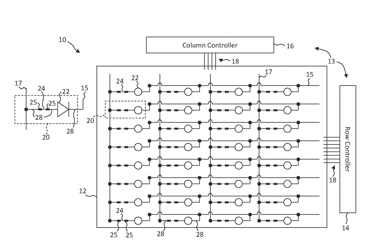
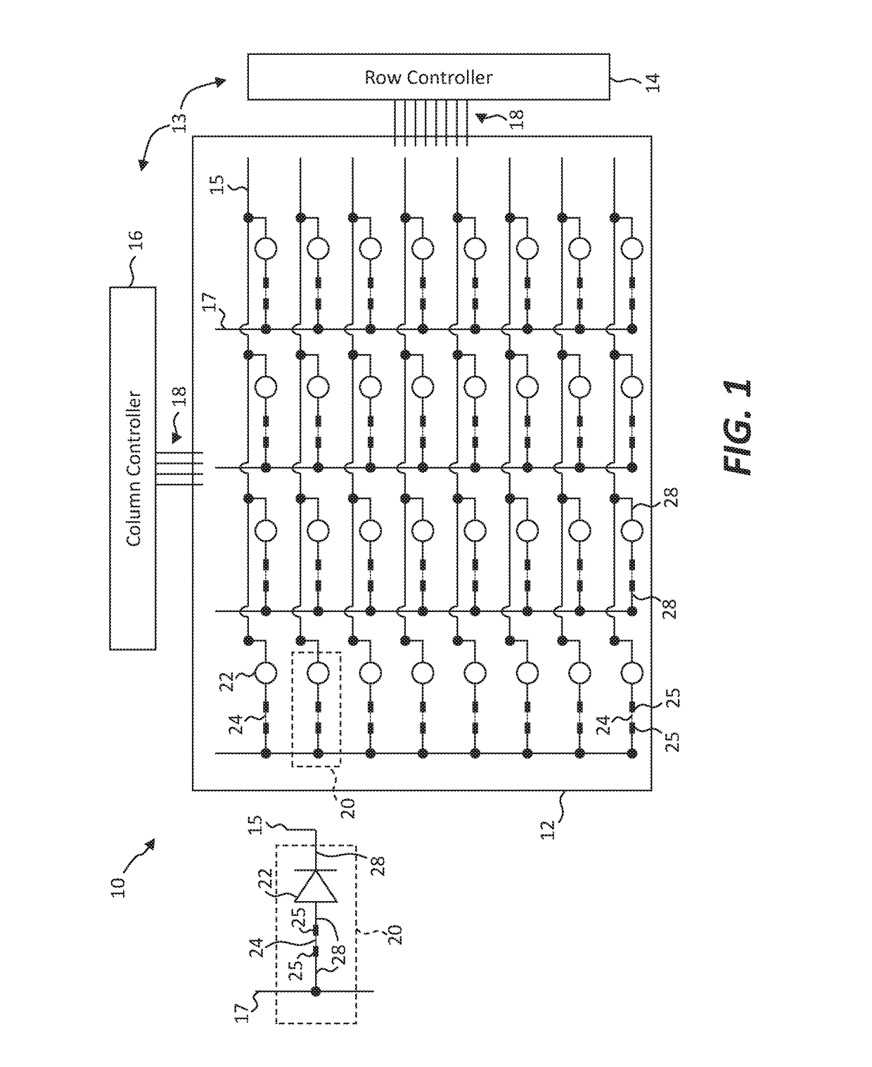
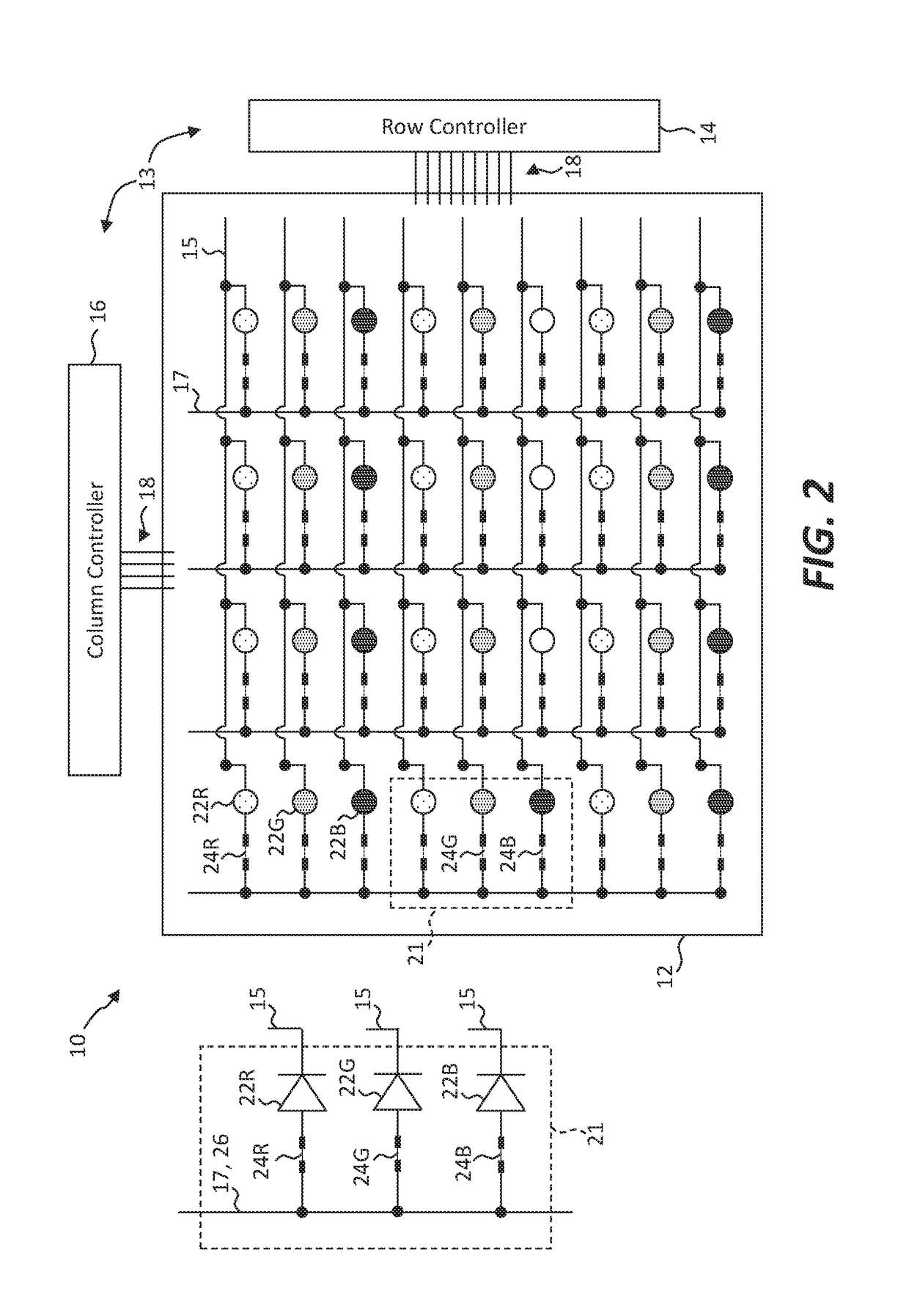
[0084]The present invention includes embodiments of a display 10 having an array of fused light-emitting diodes (LEDs) 22, as illustrated in FIG. 1. The display 10 includes a display substrate 12 with an array of pixel components 20 disposed on, over, or in the display substrate 12. Each pixel component 20 has at least one light-emitting diode 22 and at least one electrical fuse 24. Each fuse 24 is electrically connected in series to at least one light-emitting diode 22, for example, with an electrode 28. Each fuse 24 can include fuse electrical contacts 25 for providing electrical connections to the fuse 24. The electrodes 28 can be or provide the fuse electrical contacts 25 or the fuse electrical contacts 25 can be or provide a portion of the electrodes 28. The electrodes 28 and the fuse electrical contacts 25 are electrical conductors and can be made of metal patterned with photolithographic methods, tools, and materials.

[0085]The display 10 can include an array of row conductors...


PUM


Abstract

A display having fused light-emitting diodes (LEDs) includes a display substrate and an array of pixel components disposed on the display substrate. Each pixel component comprises a light-emitting diode and an electrical fuse electrically connected in series with the light-emitting diode. The micro-transfer printable pixel components include an LED having first and second LED electrical contacts for providing power to the LED to cause the LED to emit light, a fuse having first and second fuse electrical contacts, the first fuse electrical contact electrically connected in series with the first LED electrical contact, a first electrode connected to the second fuse electrical contact, and a second electrode connected to the second LED electrical contact.

Description

PRIORITY APPLICATION[0001]This application claims priority to and benefit of U.S. Patent Application No. 62 / 311,288, filed Mar. 21, 2016, entitled Display with Fused LEDs, the content of which is hereby incorporated by reference in its entirety.FIELD OF THE INVENTION[0002]The present invention relates to displays with inorganic light-emitting diode pixels.BACKGROUND OF THE INVENTION[0003]Flat-panel displays are widely used in conjunction with computing devices, in portable devices, and for entertainment devices such as televisions. Such displays typically employ a plurality of pixels distributed over a display substrate to display images, graphics, or text. In a color display, each pixel includes light emitters that emit light of different colors, such as red, green, and blue. For example, liquid crystal displays (LCDs) employ liquid crystals to block or transmit light from a backlight behind the liquid crystals and organic light-emitting diode (OLED) displays rely on passing curren...

Claims


Application Information

Patent Timeline
Patent Type & Authority Applications(United States)
IPC IPC(8): G09G3/32G09G3/20
CPCG09G3/32G09G3/2003G09G2300/0452G09G2300/0426G09G2330/08H01L27/0288G09G2330/045G09G3/3216G09G3/3233G09G2300/0439G09G2330/10
Inventor MEITL, MATTHEWCOK, RONALD S.
Owner X DISPLAY CO TECH LTD
Learn More