
Faster state transitioning for continuous adjustable 3Deeps filter spectacles using multi-layered variable tint materials

a technology of multi-layered variable tinting and filter spectacles, applied in the field of motion pictures, can solve the problems of not describing any objective optimal target for those optical densities, inability to transition between optical density states that are far apart, and inability to fast transition times

Inactive Publication Date: 2017-09-21
JACOBS KENNETH +1
View PDF0 Cites 13 Cited by
  • Summary
  • Abstract
  • Description
  • Claims
  • Application Information

AI Technical Summary

Benefits of technology

The patent describes a way to create the illusion of continuous movement using a few images. By showing two similar images alternating with a different image, the viewer is led to believe they are moving in a smooth, seamless motion. This method can be done using either motion picture film or electronic media. The two images are blended together to create a more fluid or natural illusion of continuous movement. By repeating the process and adding more blended frames, the illusion can be maintained for as long as desired.

Problems solved by technology

In the presence of screen motion, they only developed 3D from a 2D movie by a difference in optical density between the right and left lens, but did not describe any objective optimal target for those optical densities.
A problem arises when 3Deeps Filter spectacles are fabricated from electronically controlled variable tint materials that are incapable of the fast transition times that are sometimes required as for instance between scene changes.
While electronically controlled variable tint materials may be able to achieve fast transitions from one optical density state to another optical density state that are near or close to each other, it may be incapable of transition between optical density states that are far apart.
Another problem relates to the cycle life (number of clear-dark cycles before failure) of some optoelectronic materials that may be limited.
Similarly, small changes during performance in speed, placement and direction of propeller spin will cause radical changes in the visual event produced onscreen.
Attempts to capture the phenomena by way of video-camera recording of the screen-image have been disappointingly compromised, so that—in over 25 years of such presentation (of so-called Nervous System Film Performances) no attempt has been made to commercialize such recordings.
The 3-D movie fad of the early to mid-1950s however soon faded due to complexity of the technologies and potential for improper synchronization, and misalignment of left and right eye images as delivered to the viewer.
For the great majority of viewers the limitation of spectacles with a fixed filter, either left or right, meant the 3D effect would be available only with movies produced specifically for that viewing spectacles design.
Despite the wide appeal to viewers, the difficulties and burden on motion picture producers, distributors, TV networks, motion picture theaters, and on the viewers has been a barrier to their wide scale acceptance.
Among the problems and constraints involving the production, projection, and viewing of 3-dimensional motion pictures are:
On a large scale this is commercially unfeasible, as special effects in a motion picture must be able to be projected with standard projection equipment in a movie theater, TV or other broadcast equipment.
From the viewer's vantage, 3-dimensional glasses, whether anaglyph glasses or Pulfrich glasses, which are used in the majority of 3-dimensional efforts, if poorly made or worn incorrectly are uncomfortable and may cause undue eyestrain or headaches.
Because of these and other problems, 3-dimensional motion pictures have never been more than a novelty.
The inconvenience and cost factors for producers, special equipment projection requirements, and viewer discomfort raise a sufficiently high barrier to 3-dimensional motion pictures that they are rarely produced.
Low light conditions can take a few thousands of a second longer to transmit signals than under higher light conditions.

Method used


Image

  • Faster state transitioning for continuous adjustable 3Deeps filter spectacles using multi-layered variable tint materials
  • Faster state transitioning for continuous adjustable 3Deeps filter spectacles using multi-layered variable tint materials
  • Faster state transitioning for continuous adjustable 3Deeps filter spectacles using multi-layered variable tint materials

Examples


embodiments

[0387]In practice, the implementation of this technique opens up a new world of visual effects. Its uncanniness may be emphasized to create unsettling time-space aberrations for comic or dramatic effect in movies. Or, aiming for more realistic appearance, the method could be used to provide more lively snapshots of familiar things and events. For instance, people could carry, programmed into a Palm Pilot-type electronic wallet, a great many (low memory demanding) moving replicas of loved ones in characteristic living gestures, with heightened 3-dimensional presence. Even very limited movement, limited 3-dimensionality, can enormously augment and reinforce visual information: i.e., a child's face breaks into a smile. Again, the very low demand of electronic memory by an Eternalism (cycling as few as two picture-frames with an interval of darkness), makes possible extensively illustrated electronic catalogues or even encyclopedias, supporting hundreds and eventually thousands of Etern...

first alternate embodiment

A First Alternate Embodiment

[0569]Motion pictures are often viewed on small, personal devices such as an Apple iPod. Such devices have small screens and are held within arms reach for viewing. For such devices the preferred embodiment that optimizes the Optical Density of the neutral density lens to an average inter-ocular distance may be inappropriate. We provide other alternate embodiments, either of which is appropriate for small viewing devices, as well as for TV or movie theater viewing.

[0570]FIG. 43 shows the use of the retinal reaction time curve 3710 for a first alternate embodiment algorithm 4300 to calculate the optical density of the neutral density lens. The x-axis 3701 shows luminance, and the y-axis 3703 shows retinal reaction time. Observe that the amount of light produced by a motion picture is constantly changing. Some night scenes in a movie produce low light, and other scenes such on the open seas at noon are much brighter. In this first alternate embodiment, rath...

second alternate embodiment

A Second Alternate Embodiment

[0574]FIG. 45 uses the typical curve 3710 of retinal reaction time 3703 as a function of Luminance 3701 to demonstrate a second alternate embodiment 4500 for computing an optimal optical densities for the neutral density lens of the Continuous Alternating 3Deeps Filter Spectacles so that the difference (Δ) 4518 in retinal reaction time between the viewer's eyes corresponds to a fixed number of frames of the motion picture.

[0575]In this second alternate embodiment, rather choose an optical density for the neutral filter so that there is a separation of the average inter-ocular distance (2½ inches) between the instant and delayed image to the eye (as in the preferred embodiment), we may choose to have a difference (Δ) 4518 between retinal reaction time chosen so that the instant and lagging image are a fixed number of movie frames. It will be seen that this has some advantages.

[0576]In this example, assume as in FIG. 40 that the luminance 4510 is 0.54. Thi...


PUM


Abstract

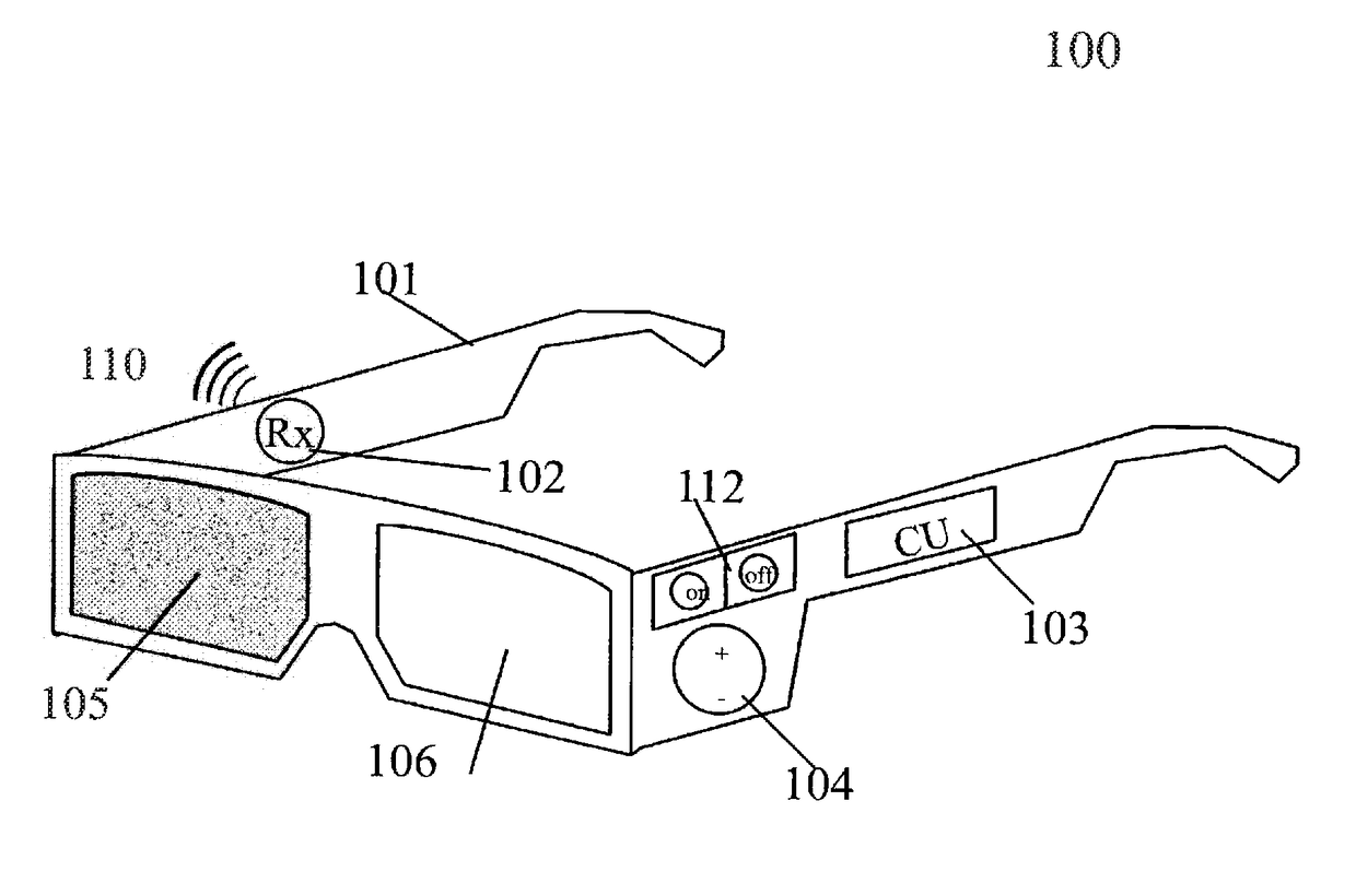
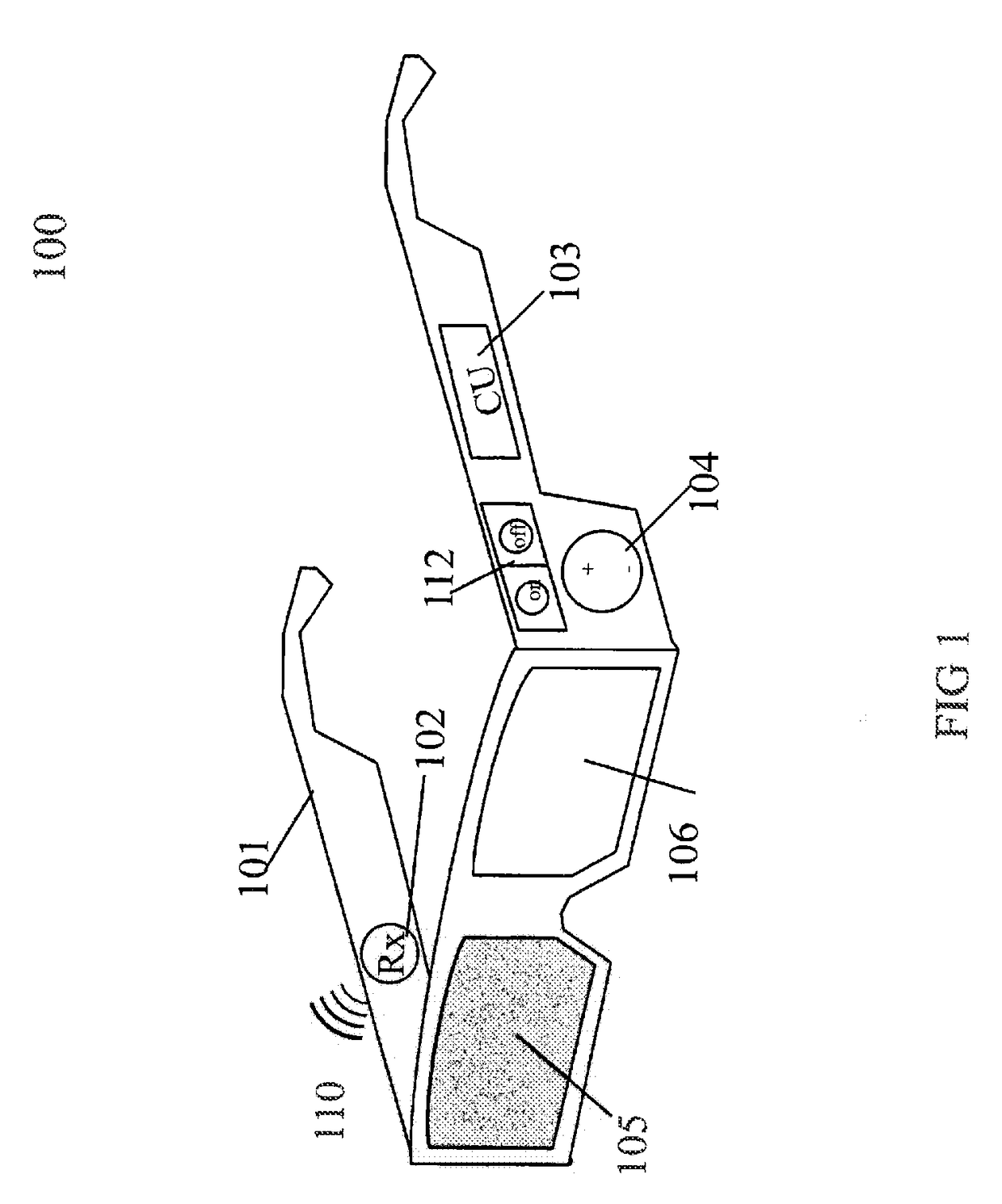
An electrically controlled spectacle includes a spectacle frame and optoelectronic lenses housed in the frame. The lenses include a left lens and a right lens, each of the optoelectrical lenses having a plurality of states, wherein the state of the left lens is independent of the state of the right lens. The electrically controlled spectacle also includes a control unit housed in the frame, the control unit being adapted to control the state of each of the lenses independently.

Description

CROSS REFERENCE TO RELATED APPLICATIONS[0001]This application is (I) a Continuation-In-Part application of U.S. patent application Ser. No. 15 / 217,612, filed Jul. 22, 2016, which is a Continuation of U.S. patent application Ser. No. 14 / 850,750, filed Sep. 10, 2015, now U.S. Pat. No. 9,426,452, which is a Continuation of U.S. patent application Ser. No. 14 / 451,048, filed Aug. 4, 2014, now U.S. Pat. No. 9,167,235, which is a Continuation of U.S. patent application Ser. No. 14 / 155,505, filed Jan. 15, 2014, now U.S. Pat. No. 8,864,304, which is a Continuation of U.S. patent application Ser. No. 13 / 746,393, filed Jan. 22, 2013, now U.S. Pat. No. 8,657,438, which is a Continuation of U.S. patent application Ser. No. 12 / 938,495, filed Nov. 3, 2010, which is a Divisional of U.S. patent application Ser. No. 12 / 555,545, filed Sep. 8, 2009, now U.S. Pat. No. 7,850,304, which is a Continuation-In-Part application of U.S. patent application Ser. No. 12 / 274,752, filed Nov. 20, 2008, now U.S. Pat....

Claims


Application Information

Patent Timeline
Patent Type & Authority Applications(United States)
IPC IPC(8): H04N13/04G02B26/02G02B27/01G02B27/22G02C11/00G02C7/00G02C7/10H04N13/00H04N13/02
CPCG02B26/026G02B27/017G02B27/0172G02B27/2221G02B27/2264G02B2027/014G02C7/101H04N13/0033H04N13/026H04N13/0431H04N13/0434H04N13/0438H04N13/0454H04N13/0497H04N2213/002H04N2213/008G02C7/00G02B27/2228H04N13/0429H04N13/0425H04N13/0422G02C11/10H04N2013/0077H04N2013/0096G02B27/2207G02B30/40H04N13/144H04N13/261H04N13/334H04N13/337H04N13/341H04N13/359H04N13/398G02B30/23G02B30/24G02B30/34H04N13/324H04N13/327H04N13/332
Inventor JACOBS, KENNETH MARTINKARPF, RONALD STEVEN
Owner JACOBS KENNETH
Learn More