
Method and device for monitoring deformation of base point of dam abutment

A monitoring device and dam abutment technology, which is applied to measurement devices, optical devices, instruments, etc., can solve the problems of complex monitoring methods and low measurement accuracy, and achieve the effects of high cost performance, high measurement accuracy and simple structure.

Inactive Publication Date: 2012-07-04
霍海清 +1
View PDF4 Cites 15 Cited by
  • Summary
  • Abstract
  • Description
  • Claims
  • Application Information

AI Technical Summary

Problems solved by technology

[0003] In order to solve the problem that the existing dam abutment base point deformation monitoring method is complex and the measurement accuracy is not high, and improve the safety of the dam in use, the present invention provides a high-precision, real-time monitoring large-scale monitoring method based on the principle of binocular stereo vision Method and device for deformation of base point of dam abutment

Method used


Image

  • Method and device for monitoring deformation of base point of dam abutment
  • Method and device for monitoring deformation of base point of dam abutment
  • Method and device for monitoring deformation of base point of dam abutment

Examples


Embodiment Construction

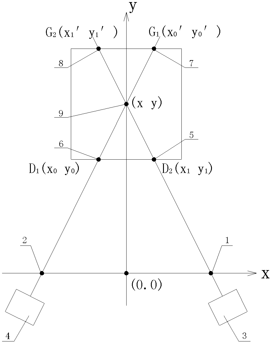
[0021] Such as figure 1 As shown, a monitoring method for the deformation of the base point of the dam abutment includes:

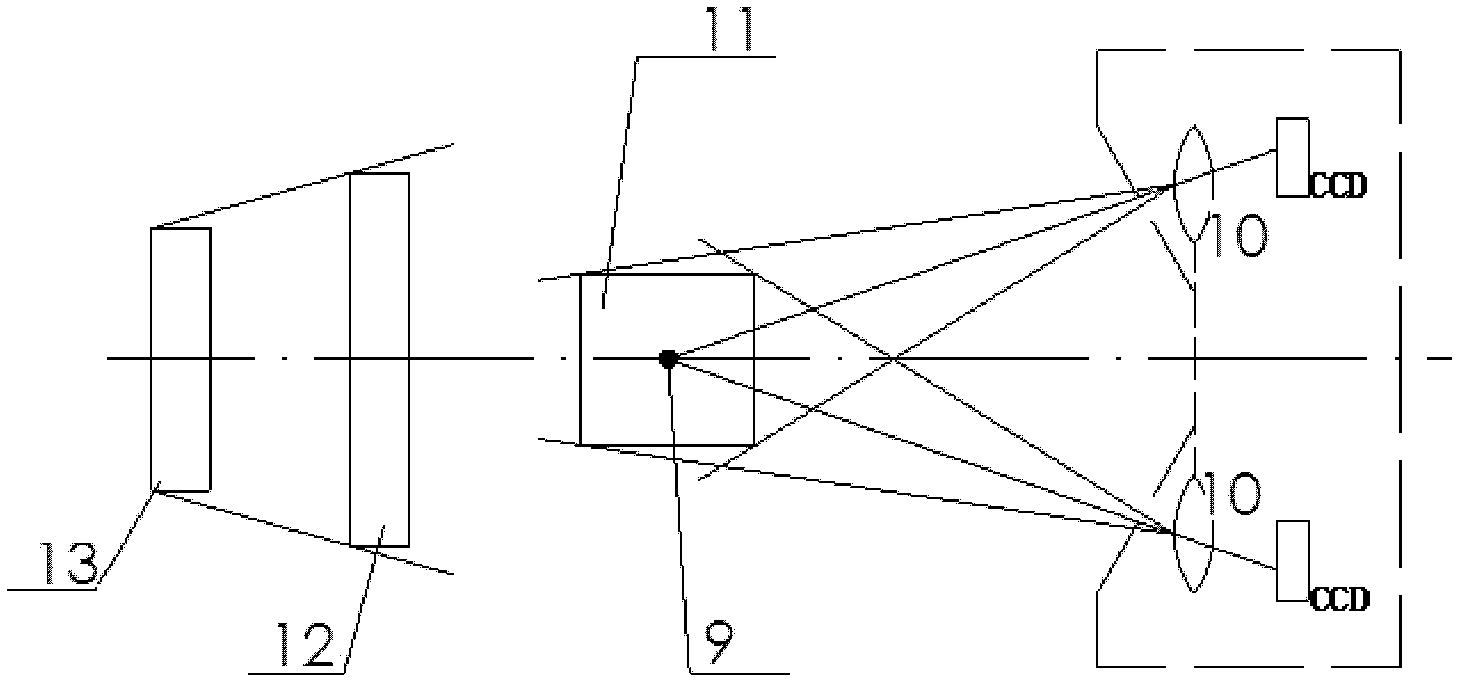
[0022] 1) Install a set of optical imaging measurement system at the foundation point of the dam abutment. The light source part of the optical imaging measurement system is a wide field of view uniform light formed by a surface light source 13 (background light source) and an acrylic plate 12. The imaging measurement part It is connected by the vertical line 9 fixed at 30m below the bedrock, the left and right lenses 2, 1 (lens 10), the left and right photoelectric devices 4, 3 (line array or area array CCD, or CMOS), and the photoelectric devices Composed of a circuit board and a communication system, the vertical line 9 is placed on the vertical line connecting the optical centers of the left and right lenses during calibration, and the light on the surface light source passes through the acrylic plate and is evenly projected on the vertical line 9, pa...


PUM


Abstract

The invention discloses a method and a device for monitoring deformation of a base point of a dam abutment. The invention is characterized in that: when an object to be detected is placed in a light path, a background light source penetrates through a left lens and a right lens to project the object to be detected on a left charge coupled device (CCD) and a right CCD; center-of-gravity coordinates of a projection on a target surface of each of the left and right CCDs are extracted; according to a binocular stereo vision principle, a transformation relational expression of the center-of-gravity coordinates of each projection and the left position of the actual object to be detected is obtained; the coordinate position of the object to be detected in a measuring range is computed; when the position of the center of gravity of each projection is changed, the change of the position of the object to be detected can be obtained; and when a dam body moves, the projections on the target surfaces of the two CCDs can move correspondingly, and the actual movement distance of the object to be detected can be obtained by computing the movement distance of the center of gravity of each projection through formula transformation.

Description

technical field [0001] The invention relates to a measuring device and method, in particular to a method and device for real-time monitoring of the deformation of the base point of the dam abutment based on the principle of binocular stereo vision. Background technique [0002] At present, there are relatively few devices and methods for real-time deformation monitoring of the dam abutment base point in China, and the existing measurement methods are too complicated and the measurement accuracy is not high, or the measurement method is simple and cannot accurately measure the dam base point. The amount of deformation cannot be accurately collected in real time, which brings inconvenience to the dam monitoring personnel on the deformation and safety judgment of the dam abutment base point. Contents of the invention [0003] In order to solve the problem that the existing dam abutment base point deformation monitoring method is complex and the measurement accuracy is not hig...

Claims


Application Information

Patent Timeline
IPC IPC(8): G01B11/16
Inventor 霍海清马丹
Owner 霍海清
Learn More