Heelless athletic shoe

a technology of athletic shoes and heels, applied in the field of shoes, can solve the problems of increasing the number of injuries incurred during such activities, the absorption of high-plied heels is not sufficient to reduce the number of injuries, and the padding cannot substitute, so as to promote an appropriate posture or gait, and inhibit the landing of heels

Inactive Publication Date: 2017-09-28
PENKA ETIENNE
View PDF14 Cites 14 Cited by
  • Summary
  • Abstract
  • Description
  • Claims
  • Application Information

AI Technical Summary

Benefits of technology

[0014]In accordance with this invention an embodiment of a heelless shoe has an upper including a toe portion, a midsection and a rear portion and a multiple part sole forming an interior volume for receiving an individual's foot. The multiple part sole comprises an inner sole for engaging the plantar surface of the foot, a midsole having an inner surface attached to the exterior of the inner sole to be substantially coextensive with the inner sole, the midsole having an outer surface, and an outer sole attached to the outer surface of the midsole intermediate the inner and outer soles. The outer sole has a first portion extending from the proximal end of the shoe to a position under the foot selected according to an intended use of the shoe and a second contiguous portion extending from the selected position to the distal or rear portion of the shoe. The first portion of the outer sole provides a landing surface for the shoe and the second, relatively thin portion as compared to the first portion thereby inhibiting landings on the heel for different embodiments of the shoe and generally promoting an appropriate posture or gait for the wearer while performing the motions involved in the selected activity.

Problems solved by technology

Despite many advances in the design and construction of athletic shoes, injuries incurred during such activities continue to be widespread.
Frequently it is the way an individual lands and then steps off that leads to these injuries.
This foot position minimizes the natural shock absorbing capacity of the foot and often leads to the previously discussed injuries.
Frequently they revert to a heel landing when they become fatigued or otherwise distracted or preoccupied.
Consequently, even highly padded heels do not provide a sufficient absorption to reduce the number of injuries to individuals.
That is, reasonable levels of padding cannot substitute for the shock absorbing system in an individual's forefoot.
However, the prior art does not specify the depth or thickness and the length of the recess area appropriate for different individuals who engage in different types of activities at different levels of skill.

Method used


Image

  • Heelless athletic shoe
  • Heelless athletic shoe
  • Heelless athletic shoe

Examples


example 1

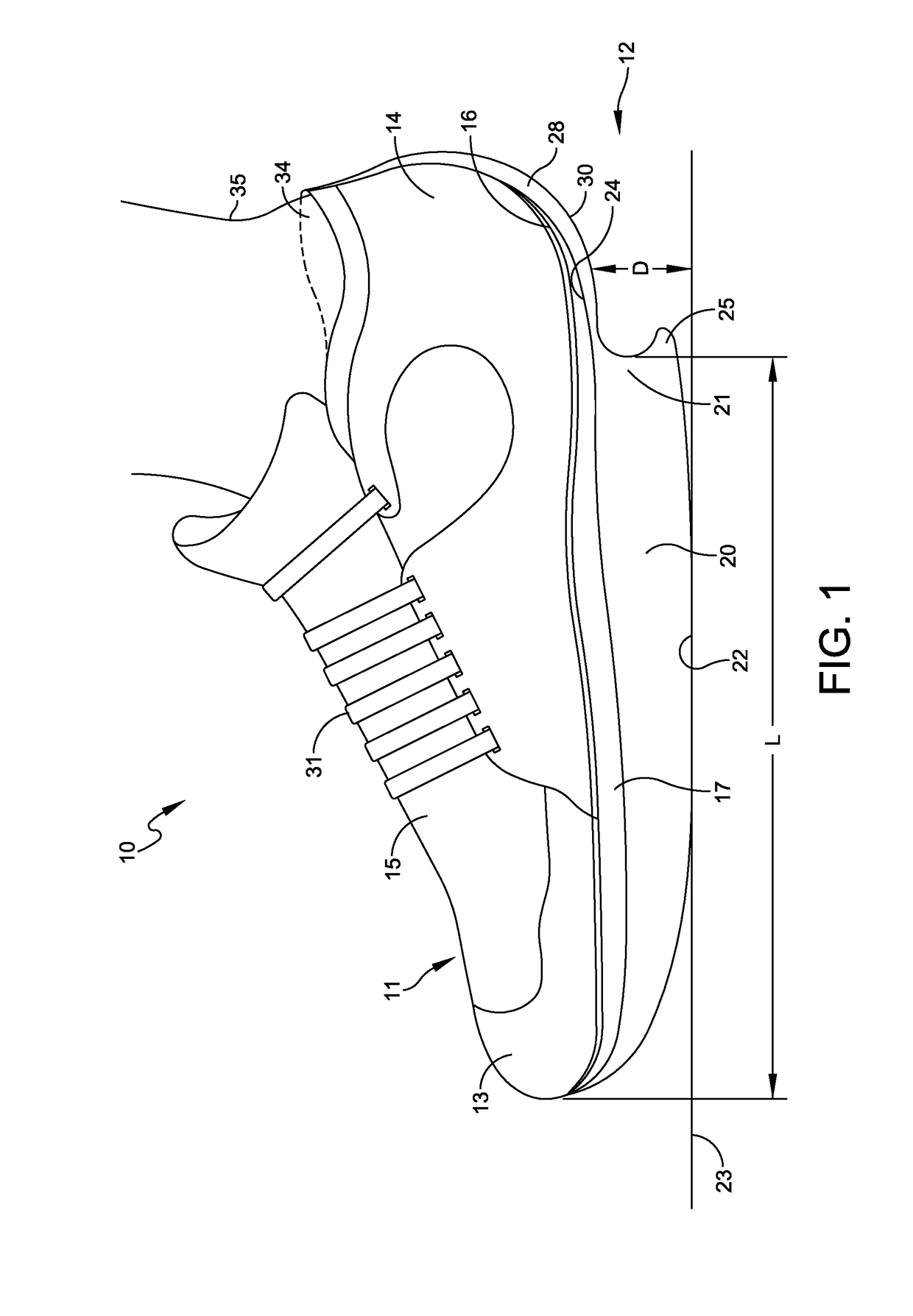
[0039]As an example of how an athletic shoe according to the present invention might be properly tailored to a particular individual, assume the intended wearer is a middle-aged woman who wants to lose extra weight by engaging in walking. This individual has had a previous injury to her right knee which may be aggravated by heel strikes while walking. According to FIG. 3, an appropriate length L=a is recommended for the individual by the professional fitting her for a shoe who would also determine her proper shoe size. Because the individual is overweight and has a history of injury, the professional selects a recess depth D of 10 mm for the right shoe to be worn by this individual to both provide appropriate cushioning and comfort while preventing heel strikes which may aggravate her previous injury. As known in the art, additional support features not limited to this invention may be included in the structure of the shoe. The professional fitting this woman might select a similar ...

example 2

[0040]As a second example, assume the intended wearer of the shoe is a relatively fit college runner who competes in middle-distance races. The professional fitting the shoe selects a length L=c for the landing surface 22 (FIG. 3), and a 3 mm depth of recess D for this runner. As discussed previously, a more competitive middle-distance runner will land on the running surface with her body weight more forward on the forefoot and is sufficiently fit such that having less cushioning on the landing surface of the shoe resulting in greater impact force on the foot is an acceptable compromise to achieve better performance provided by a quicker landing and step off.

example 3

[0041]Altering the scenario above such that the middle-distance runner, though fit, has had a prior injury to her right knee, a 10 mm depth of recess D might be appropriate to provide some cushioning with protection from heel strikes or discomfort while still providing acceptable performance characteristics for the competitive runner. The possible variations of this invention are numerous, but the utility of the invention in many possible scenarios should now be apparent to one skilled in the art.

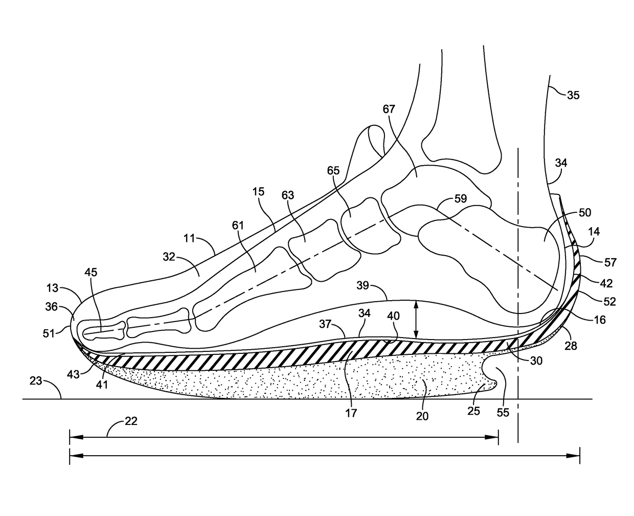
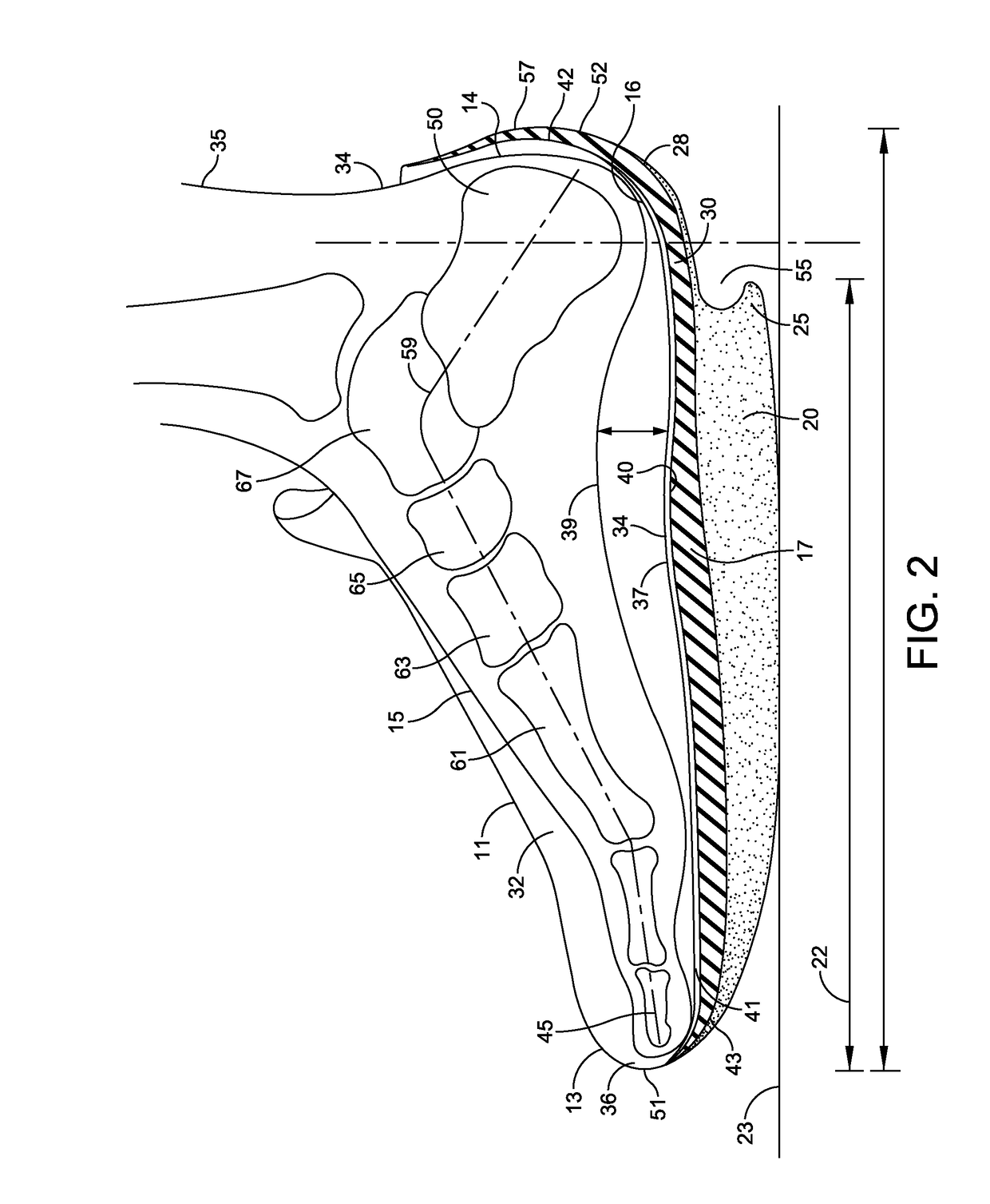
[0042]In summary, an athletic shoe 10 constructed in accordance with this invention includes a proximal sole portion of a multiple part sole with a landing surface composed of a pressure deformable material under at least part of the forefoot, with the exception of L=g (need clarification here). The extent and thickness of the landing surface constructed for a particular embodiment of the shoe is determined with reference to a grid matching possible intended uses for the shoe to a suggested...


PUM

PropertyMeasurementUnit
depthaaaaaaaaaa
depthaaaaaaaaaa
volumeaaaaaaaaaa

Abstract

A grid for selecting an appropriate embodiment of an athletic shoe having an upper and a multiple part sole forming an interior volume for receiving an individual's foot. The multiple part sole comprises an inner sole for engaging the plantar surface of the foot, a midsole attached to the exterior of the inner sole and substantially coextensive with the inner sole, and an outer sole attached to the midsole. The outer sole has a first portion extending from the toe of the shoe to a position beneath the foot selected according to the intended use of the shoe, and has a second contiguous portion extending from the selected position to the heel of the shoe, the first portion providing a landing surface for the shoe and the second portion being relatively thin as compared to the first portion thereby promoting proper posture and gait of the wearer.

Description

BACKGROUND OF THE INVENTION[0001]Field of the Invention[0002]This invention generally relates to footwear and more particularly to shoes for use in athletics and rehabilitation that are tailored for a specific activity and a level of the wearer's expertise for that activity.[0003]Description of Related Art[0004]Shoes suited for physical activities, such as running, jogging, brisk walking, aerobic exercise and the like which involve stepping and landing on an individual's feet are well known. Generally these activities are characterized by suspension and landing of the foot. In such physical activities the individual's foot acts as a shock absorber upon landing, a support member during the period between landing and stepping off, and a spring for propelling, launching, or stepping from the surface such as the ground. Despite many advances in the design and construction of athletic shoes, injuries incurred during such activities continue to be widespread. Such injuries include heal sp...

Claims


Application Information

Patent Timeline
Patent Type & Authority Applications(United States)
IPC IPC(8): A43B13/12A43B13/04A43B5/00A43B13/18
CPCA43B13/122A43B13/187A43B5/00A43B13/181A43B13/04A43B13/12A43B23/0245A43B7/142A43B7/1425A43B7/143A43B7/1435A43B7/1445A43B7/145A43B13/145A43B13/148
Inventor PENKA, ETIENNE
Owner PENKA ETIENNE
Why Eureka
Try Eureka