Injection molding controller interface with user-adjustable variables

a controller and variable technology, applied in the field of injection molding, can solve the problems of inability to adjust as frequently as optimal, affecting the efficiency of injection molding machines, etc., to achieve the effect of effective control of the operation of injection molding machines and increasing efficiency and outpu

Active Publication Date: 2017-09-28
IMFLUX INC
View PDF0 Cites 10 Cited by
  • Summary
  • Abstract
  • Description
  • Claims
  • Application Information

AI Technical Summary

Benefits of technology

[0008]Embodiments within the scope of the present invention are directed to the use of multiple controllers (i.e., a native controller and a retrofit controller) to effectively control operation of an injection molding machine. The controllers may determine and/or receive information regarding the machine's maximum load capacity, and may also determine an instantaneous (or at least periodic) present load value on the machine. The retrofit controller of the present disclosure may cause the machine to operate at or near the maximum load value by adjusting any number of machine parameters, and dynamically adjust the range within which operator-adjustable parameters in an injection molding operation may be manipulated to facilit

Problems solved by technology

In the event that the manufacturer's safety margin level, as contrasted to the machine's actual maximum load value for a given set of operating and environmental conditions, is exceeded, the machine may overheat, trip to a failsafe setting, and/or trigger an alarm condition.
This increase in the operational load value may eventually cause the machine to approach or exceed the maximum load value which may result in temporary or permanent machine failure.
By relying on the machine operator to adjust operating parameters of the machine, adjustments may not be made as frequently as optimal.
Further, an operator may not realize when the characteristics causing the machine's load value to change have subsided, and thus may keep the machine running in an operational mode which fails to fully utilize the injection molding machine's efficiency.
The restrictions applied to th

Method used


Image

  • Injection molding controller interface with user-adjustable variables
  • Injection molding controller interface with user-adjustable variables
  • Injection molding controller interface with user-adjustable variables

Examples


Embodiment Construction

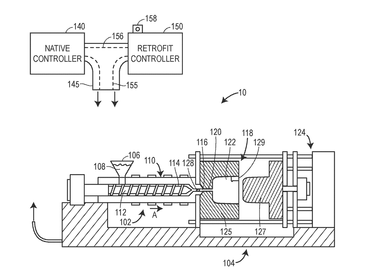
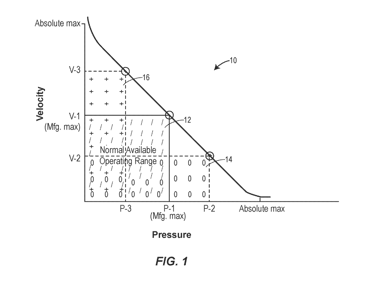
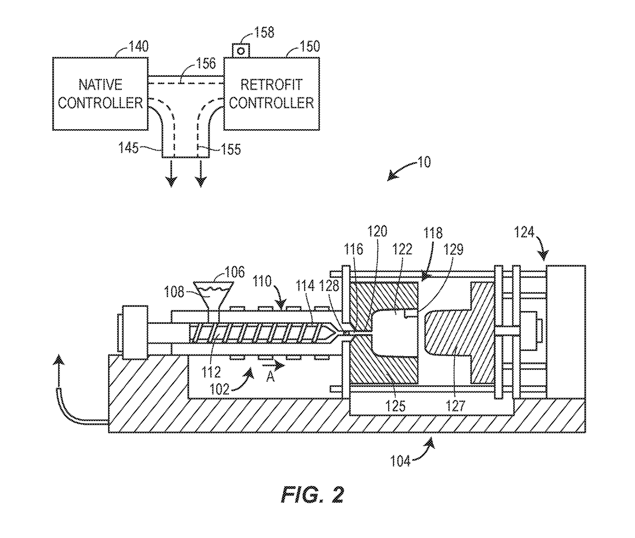
[0025]Turning now to the drawings, an injection molding process is herein described. Injection molding machines have a generally nonlinear reference or maximum loading curve 10 as illustrated in FIG. 1. This curve 10 may be viewed as a graphical representation of an effect that any number of parameters (such as, for example, velocity as a function of operating pressure) may have on the machine. Generally speaking, operators run these machines at operating load values (which may fluctuate over time) that are at a point well below the reference load curve to avoid tripping the injection molding machine manufacturer's pre-programmed alarms and / or failure modes. As FIG. 1 illustrates, injection molding machines (also referred to herein simply as “machines”) typically have absolute maximum operating values which may not be exceeded so as to limit potential machine failure.

[0026]Machine manufacturers utilize safety buffers which act to restrict parameters from exceeding particular values ...


PUM

PropertyMeasurementUnit
Fractionaaaaaaaaaa
Fractionaaaaaaaaaa
Temperatureaaaaaaaaaa

Abstract

An injection molding machine uses a native controller and a retrofit controller to effectively control its operation. The controllers may determine and/or receive information regarding the machine's maximum load capacity, and may also determine a current operational load value of the machine. The retrofit controller may cause the machine to operate at any number of combinations of settings of operational parameters which result in the machine operating at or below the maximum load value by adjusting any number of machine parameters associated with the injection molding machine based on feedback sensors measuring real-time operating conditions of the machine.

Description

FIELD OF THE INVENTION[0001]The present application generally relates to injection molding and, more specifically, to approaches for retrofitting an injection molding machine with a secondary controller to control operation thereof, which can reduce the energy required to form a molded article.BACKGROUND OF THE INVENTION[0002]Injection molding is a technology commonly used for high-volume manufacturing of parts constructed of thermoplastic materials. During repetitive injection molding processes, a thermoplastic resin, typically in the form of small pellets or beads, is introduced into an injection molding machine which melts the pellets under heat and pressure. The molten material is then forcefully injected into a mold cavity having a particular desired cavity shape. The injected plastic is held under pressure in the mold cavity and subsequently is cooled and removed as a solidified part having a shape closely resembling the cavity shape of the mold. A single mold may have any num...

Claims


Application Information

Patent Timeline
IPC IPC(8): B29C45/76B29C45/77G05B19/414B29C45/78B29C48/92G06N20/00
CPCB29C45/766G05B2219/45244B29C45/7693B29C45/77G05B19/414B29C2945/76006B29C2945/7611B29C2945/76033B29C2945/7621B29C2945/76187B29C2945/76531B29C2945/76498B29C2945/76595B29C2945/76561B29C2945/76665B29C2945/76668B29C2945/76702B29K2105/0067B29K2105/251G05B2219/50168B29C45/78B29C45/7666B29C2945/76949B29C2945/76953B29C2945/7604B29C48/92B29C2948/924B29C2948/92019B29C2948/92209B29C2948/92409B29C2948/92895G06N20/00B29C45/76G05B2219/23422G05B2219/2624
Inventor ALTONEN, GENE MICHAELBURNS, BRIAN MATTHEWHANSON, III, HERBERT KENNETH
Owner IMFLUX INC
Why Eureka
Try Eureka