Method and apparatus for power supply controlling capable of effectively controlling switching operations

a technology of power supply control and switching operation, applied in the direction of electric variable regulation, process and machine control, instruments, etc., can solve the problems of significant low efficiency, low power, and extremely small current in the switching element in the light load operation

Inactive Publication Date: 2007-08-28
RICOH ELECTRONIC DEVICES CO LTD
View PDF18 Cites 21 Cited by
  • Summary
  • Abstract
  • Description
  • Claims
  • Application Information

AI Technical Summary

Benefits of technology

[0036]An object of the present invention is to provide a novel switching regulator for power supply controlling capable of effectively controlling operations of switching transistors to minimize power consumption of the switching regulator due to charging and discharging operations of parasitic capacitances.

Problems solved by technology

However, while being highly efficient in a rated load, the switching regulator consumes a relatively large amount of power for driving itself, resulting in a significantly low efficiency when an apparatus is in a mode consuming lower power than in a normal operation mode.
However, since a power consumed in the switching element is a product of a current in the switching element and a voltage applied to the switching element, the current in the switching element is extremely small in the light load operation, especially in the standby mode.
A large amount of power consumption in the light load operation is power consumed to charge and discharge a parasitic capacitance as a drive pulse existing between a control electrode and input and output terminals of the switching element.
In this technique, however, the switching frequency may have a limitation to be reduced no lower than 20 kHz.
However, the series regulator includes a voltage control transistor that causes power loss.
Even though the series regulator effectively works when a load current in the light load mode is small, the efficiency may become smaller when the load current in the light load mode becomes larger.
In addition, a size of the series regulator may cause another problem since adding the series regulator may need a larger scale of a circuit.

Method used


Image

  • Method and apparatus for power supply controlling capable of effectively controlling switching operations
  • Method and apparatus for power supply controlling capable of effectively controlling switching operations
  • Method and apparatus for power supply controlling capable of effectively controlling switching operations

Examples


Embodiment Construction

[0071]In describing preferred embodiments illustrated in the drawings, specific terminology is employed for the sake of clarity. However, the disclosure of this patent specification is not intended to be limited to the specific terminology so selected and it is to be understood that each specific element includes all technical equivalents that operate in a similar manner.

[0072]Referring now to the drawings, wherein like reference numerals designate identical or corresponding parts throughout the several views, preferred embodiments of the present invention are described.

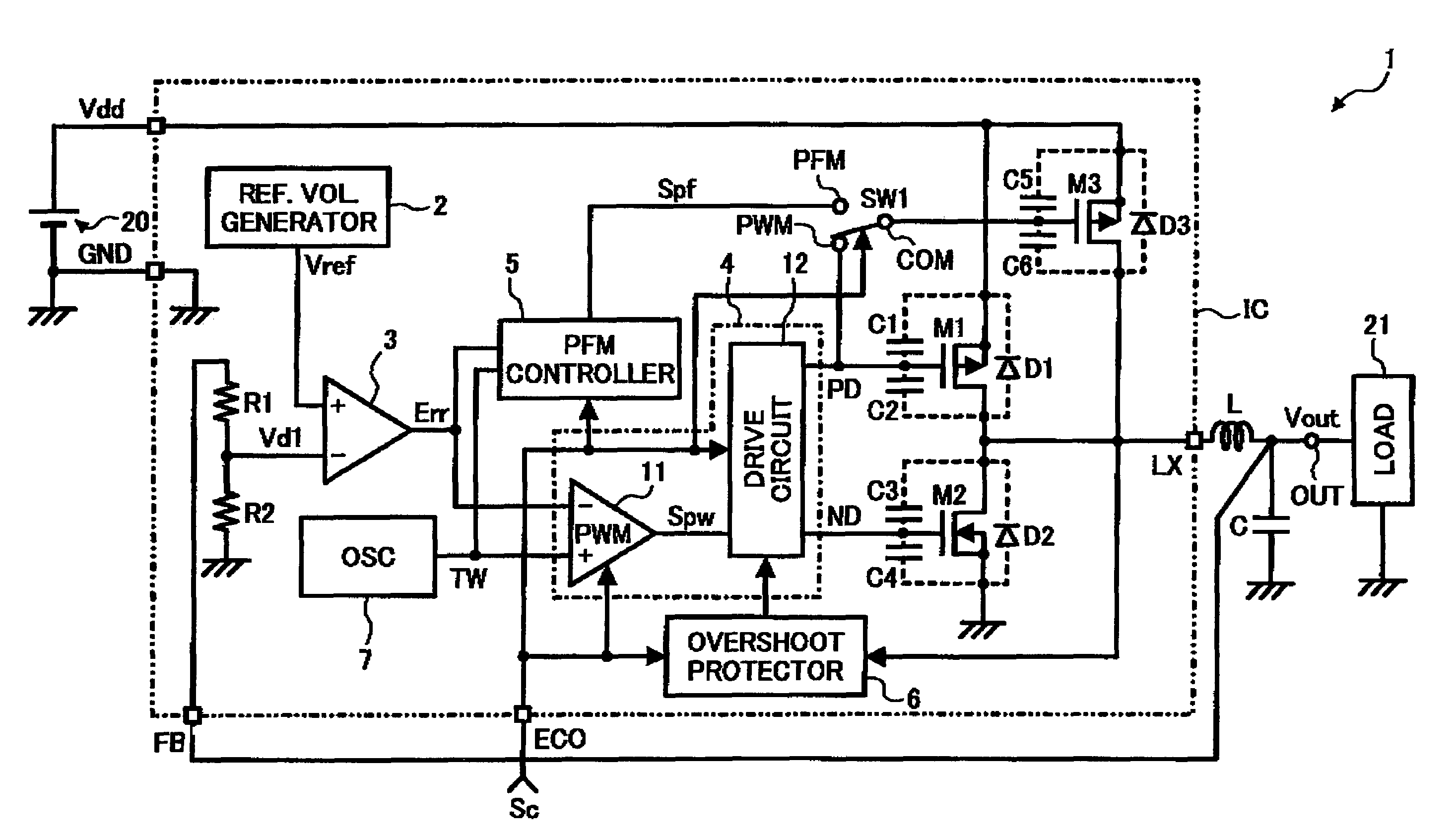
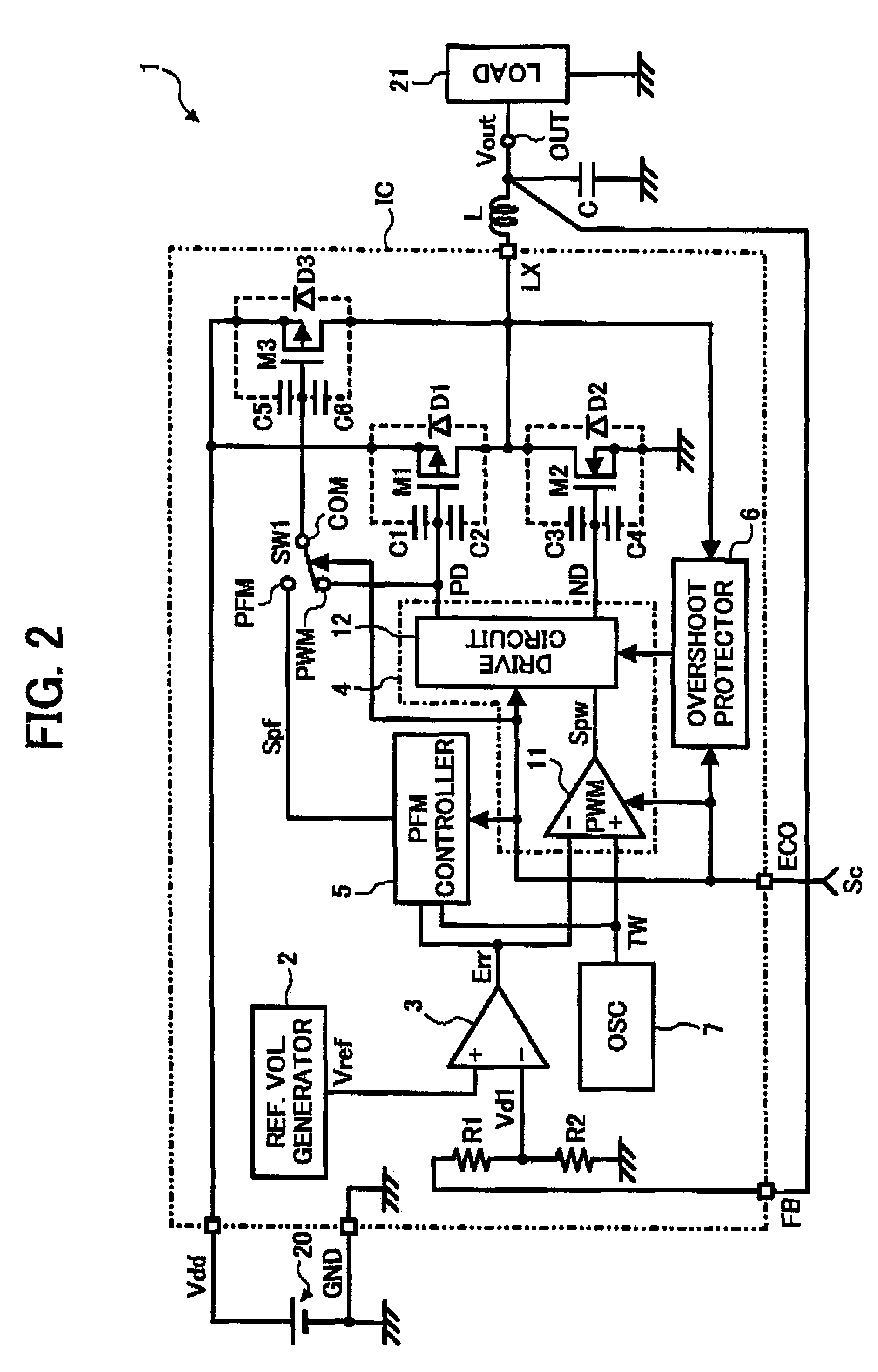
[0073]Referring to FIG. 2, a schematic structure of a switching regulator 1 according to an exemplary embodiment of the present invention is described.

[0074]In FIG. 2, the switching regulator 1 includes a first switching transistor M1 as a first switching element, a synchronous rectifying transistor M2 as a synchronous rectification switching element, and a second switching transistor M3 as a second switching element...


PUM


Abstract

A switching regulator includes a first switching element to perform a switching operation in accordance with a first control signal input thereto to control an output voltage based on an input voltage, a second switching element having a size smaller than the first switching element to perform a switching operation in accordance with one of the first control signal and a second control signal input thereto to control an output voltage based on the input voltage, and a control circuit to control the first and second switching elements to perform the switching operations in one of a normal operation mode and a light load operation mode in which a current consumed by a load connected to the switching regulator is smaller than a current consumed in the normal operation mode, and control the first switching element to be turned off in the light load operation mode.

Description

CROSS-REFERENCE TO RELATED APPLICATIONS[0001]Not applicable.STATEMENT REGARDING FEDERALLY SPONSORED RESEARCH OR DEVELOPMENT[0002]Not applicable.REFERENCE TO A COMPACT DISK APPENDIX[0003]Not applicable.BACKGROUND OF THE INVENTION[0004]The present application claims priority to Japanese patent application, No. JPAP 2003-397683 filed on Nov. 27, 2003, the entire contents of which are incorporated by reference herein.[0005]1. Field of the Invention[0006]The present invention relates to a method and apparatus for power supply controlling. In particular, the present invention relates to a method and apparatus for power supply controlling capable of effectively controlling switching operations.[0007]2. Description of the Related Art[0008]In recent years, energy saving has strongly been demanded for environmental reasons. In a portable information handling apparatus using batteries, such as a cellular phone, mobile personal information terminal, digital camera, laptop personal computer, and...

Claims


Application Information

Patent Timeline
Patent Type & Authority Patents(United States)
IPC IPC(8): G05F1/40H02M3/155H02M3/158
CPCH02M3/1584H02M2001/0032Y02B70/16H02M1/0032Y02B70/10
Inventor MATSUO, MASAHIROKATOH, TOMONARI
Owner RICOH ELECTRONIC DEVICES CO LTD
Why Eureka
Try Eureka