Electronic connector device

a technology of electronic connectors and connectors, which is applied in the direction of semiconductor devices for light sources, lighting and heating apparatus, and light support devices, etc., can solve the problems of complicated combination and production process, long complicated wire inserts in light devices, etc., to simplify the structure of the whole electrical connector, simplify the structure of the input terminal, and the effect of simple structur

Active Publication Date: 2017-09-28
XIAMEN ECO LIGHTING CO LTD
View PDF9 Cites 4 Cited by
  • Summary
  • Abstract
  • Description
  • Claims
  • Application Information

AI Technical Summary

Benefits of technology

[0006]Comparing with the existed technology, the electronic connector device fixes the input terminal on the light source board and relates the input terminal on the output terminal elastically by setting the output terminal on the driver board surface. Because the output terminal is directly set on the surface of the driver board. When the other end of the input terminal is related to the output terminal elastically, the driver board may support the output terminal to make sure the connection between the input terminal and output terminal. Because the input terminal is fixed by the driver board, the structure of the input terminal become easier. Efficiently Simplifying the structure of the whole electrical connector to make the electronic connector device owns the advantage of the simple structure.

Problems solved by technology

Because of the small space in the light device, the longer wire insert in the light device with messy is easy to make the phenomenon of the wire broken and the loosing wire welding.
The connected way needs to use the insert to realize the electronic connection, but the combination and the production process are all complicated.

Method used


Image

  • Electronic connector device
  • Electronic connector device
  • Electronic connector device

Examples


Embodiment Construction

[0011]Though the attached drawing and the embodiment to describe the present invention detailed in following statement.

[0012]The first embodiment of the present invention, the electronic connector device, please refer to FIG. 1 to FIG. 4.

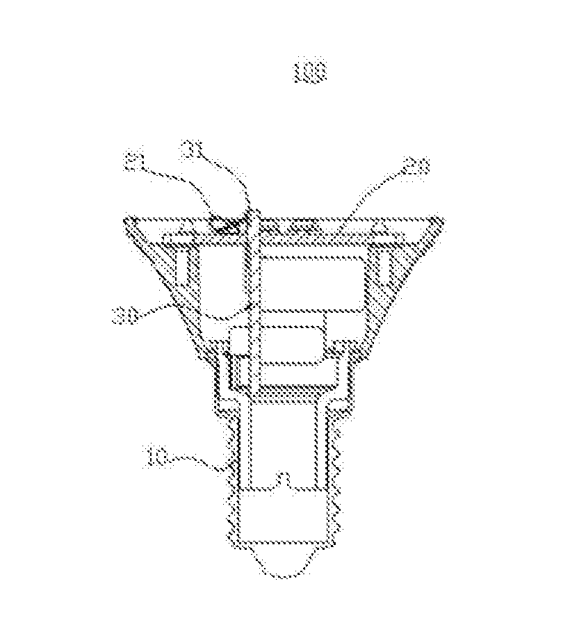
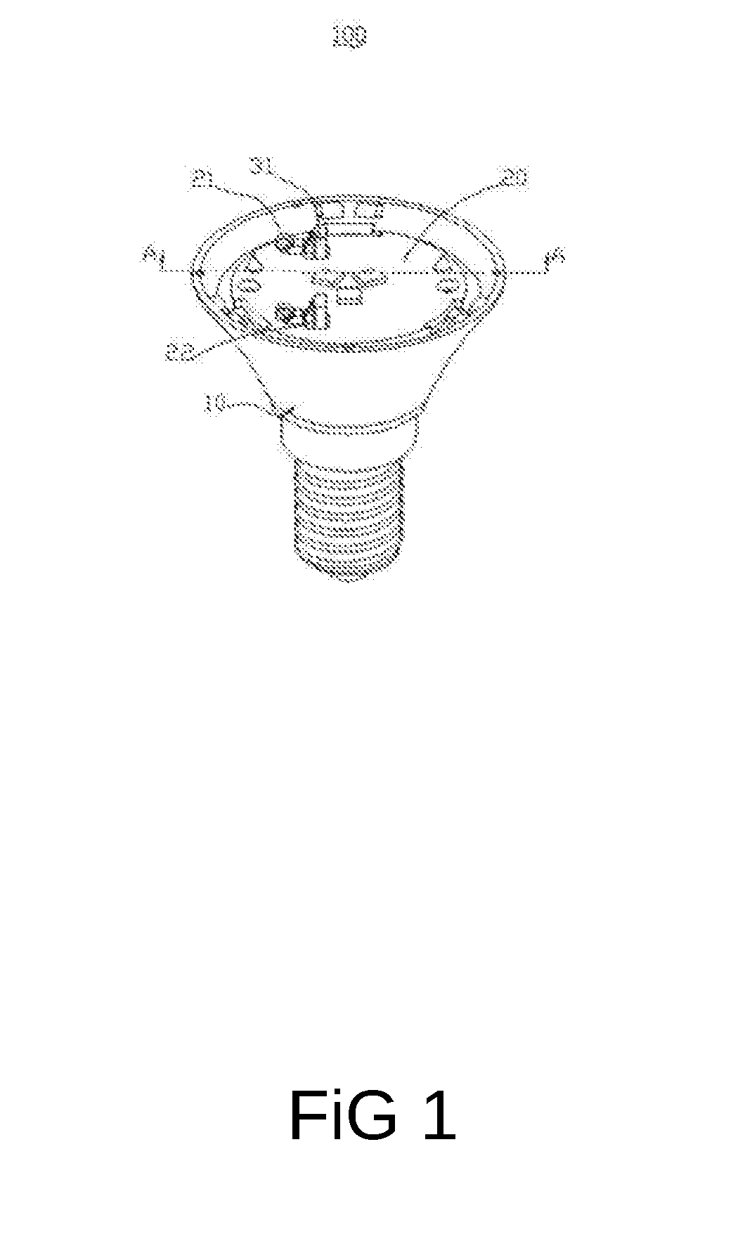
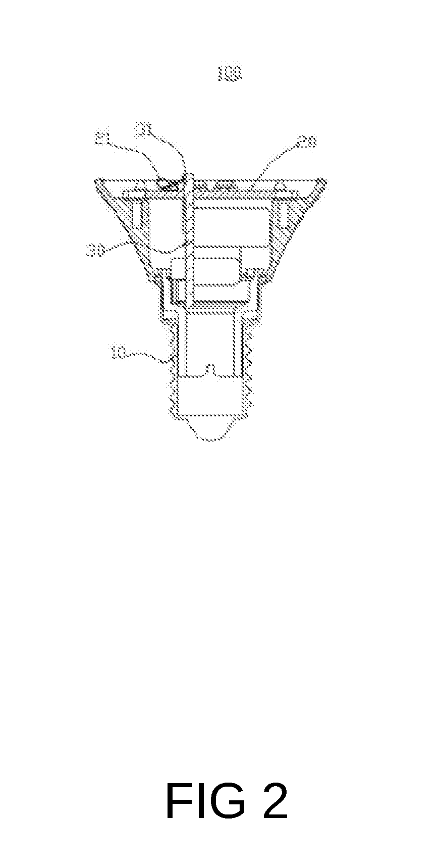
[0013]Please refer to FIG. 1 and FIG. 2, an electronic connector device is set in a light head (10). The light head (10) is the common combination of the LED shell and the screw light head, and surely may be another way of the light shell structure. The light head (10) is hollow shell structure, there is a light source board (20) and a driver board (30) in the light head (10). The electronic connector device is separately set on the light source board (20) and the driver board (30). The electronic connector device is used in the electrical connection of the light source board (20) and the driver board (30). The electronic connector device includes an input terminal (21) and an output terminal (31). The output terminal (31) is set on the surface of t...


PUM


Abstract

An electronic connector device is used to connect the light source board and the driver board of the LED light electrically. One end of the input terminal is fixed on the light source board and connect to the light source board electrically. The other end of the input terminal is the elastic clip structure. When the light source board is relatively combined with the driver board and the diver board is set near the light source board, the other end of the input terminal connects on the output terminal elastically. In the present invention, the electronic connector device fixes the input terminal on the light source board and relates the input terminal on the output terminal elastically by setting the output terminal on the driver board surface. Efficiently simplifying the structure of the whole electrical connector to make the electronic connector device owns the advantage of the structure.

Description

TECHNICAL FIELD[0001]The present invention is related to an LED lighting field and more particularly related to an electronic connector device.BACKGROUND[0002]An LED light source is used more and more widely, because the LED light source owns the advantages of high-efficiency lighting, low heating, power saving and long life time. The LED light gradually replaces the traditional lighting devices like an incandescent lamp and a halogen lamp. Nowadays, an LED bulb includes a light head, power supply board components, a lighting heat dissipation item and a lampshade. Between a light head and power supply board components; power supply board components and a lighting heat dissipation item all use the wire welding or use a screw press the wire directly to connect electrically. Because of the small space in the light device, the longer wire insert in the light device with messy is easy to make the phenomenon of the wire broken and the loosing wire welding.[0003]Like the new type of the pr...

Claims


Application Information

Patent Timeline
Patent Type & Authority Applications(United States)
IPC IPC(8): F21V23/06F21V23/00F21V21/002
CPCF21V23/06F21V23/003F21V21/002F21V23/006F21K9/237F21K9/238F21Y2115/10H01R12/57
Inventor CHEN, XIAOBOFU, ZHONGMINGSONG, GUIJUANZENG, MAOJINLI, JIANGHUAI
Owner XIAMEN ECO LIGHTING CO LTD
Why Eureka
Try Eureka