Systems and Methods for Testing Electrical Leakage

Active Publication Date: 2017-10-05
DISRUPTIVE TECHNOLGIES RES AS
View PDF1 Cites 1 Cited by
  • Summary
  • Abstract
  • Description
  • Claims
  • Application Information

AI Technical Summary

Benefits of technology

The present patent is related to a method and device for testing a circuit under test with a power source. The method involves temporarily enabling power, measuring the first voltage across the circuit, measuring the second voltage after a test duration, and calculating the average current of the circuit based on the first and second voltage measurements. The device includes a timer module, measurement module, switch module, and sequencing module. The sequencing module is responsible for temporarily enabling power, measuring the first voltage, measuring the second voltage after the test duration, and calculating the average current of the circuit based on the first and second voltage measurements. The technical effects of this patent are facilitating efficient testing of circuits with a power source and measuring the voltage and current across the circuit to verify its functionality.

Problems solved by technology

One of the more significant obstacles to improving battery life is leakage current.
However, testing for leakage current in the nano-ampere range can be extremely challenging and time consuming due to the low current levels and capacitors that need to be charged or discharged to yield an observable voltage difference.
In the end, the overall time and cost expended on these tests can be substantial when considering the significant number of devices that need to be tested and the time it takes to test each device.
However, such a workaround requires substantial infrastructure to be carried out effectively, and even then, can still become financially impractical at some point due to the amount of infrastructure involved.
Alternatively, testing leakage current in a heavily decoupled power domain may take a significant amount of time to accumulate the necessary voltage differences due to significantly large time constants.

Method used


Image

  • Systems and Methods for Testing Electrical Leakage
  • Systems and Methods for Testing Electrical Leakage

Examples


Embodiment Construction

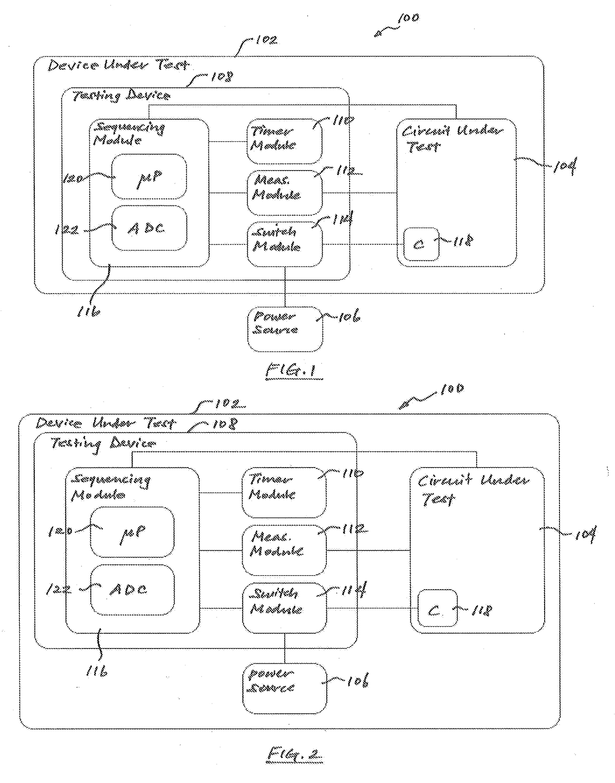
[0012]Referring now to FIG. 1, one exemplary embodiment of a testing system 100 that may be used to test for active and / or leakage current within a device under test 102 is provided. In general, the testing system 100 may include at least the circuitry of the device under test 102 to be tested, or the circuit under test 104, as well as an appropriate power supply or power source 106, and a testing device 108. In the particular embodiment shown, each of at least the circuit under test 104 and the testing device 108 may be self-contained within the device under test 102. In related modifications, the power source 106 may also be self-contained within the device under test 102. Notably, any one or more of the components of the testing device 108 and / or the power source 106 may be implemented using already existing circuit components within the device under test 102 so as to bypass the need for additional infrastructure as is typically required in conventional testing applications. More...


PUM


Abstract

A method of testing a self-contained device under test having at least a circuit under test and a power source is provided. The method may include at least temporarily enabling power from the power source to the circuit under test, determining a first voltage across the circuit under test, determining a second voltage across the circuit under test after a test duration, and calculating an average current of the circuit under test based at least partially on the first voltage, the second voltage and the test duration.

Description

CROSS-REFERENCE TO RELATED APPLICATION[0001]This application claims the benefit of priority under 35 U.S.C. §119(e) to U.S. Provisional Patent Application No. 62 / 040,659 filed on Aug. 22, 2014.TECHNICAL FIELD[0002]The present disclosure relates generally to manufacturing electrical devices, and more particularly, to systems and methods for testing leakage current in circuits of electrical devices.BACKGROUND[0003]Increasing battery lifetime is a common and often a critical concern in the development of a wide array of portable electronic devices. One of the more significant obstacles to improving battery life is leakage current. Generally, leakage current refers to undesired current flow within the circuitry of a battery-powered device which remains even after the device has been powered down or put in an off state, and active current refers to current flow within the circuitry of a battery-powered device while in an on state. In order to ensure that a manufactured device meets the d...

Claims


Application Information

Patent Timeline
IPC IPC(8): G01R31/02
CPCG01R31/2812G01R31/025G01R31/2851G01R31/52
Inventor HERNES, BJORNAR
Owner DISRUPTIVE TECHNOLGIES RES AS
Why Eureka
Try Eureka