
System and method for side insertion of a bicondylar mini knee implant

a technology of bicondylar and knee implants, which is applied in the field of resurfacing prosthesis, can solve the problems of high failure rate of unicondylar implants, large soft tissue disruption, and large scarring of major anatomical structures, and achieves improved accuracy and precision in preparation, greater spatial accuracy, and more reliable and reproducible results.

Inactive Publication Date: 2017-10-12
JOINT INNOVATION TECH LLC
View PDF2 Cites 2 Cited by
  • Summary
  • Abstract
  • Description
  • Claims
  • Application Information

AI Technical Summary

Benefits of technology

The invention is a cutting device that can be attached to a computerized actuator or mini robot to prepare bones for surgery. The main advantage of the actuator is improved accuracy and precision compared to conventional techniques. The actuator uses a synchronized computer system to precisely perform the cutting and bone resection without the need for cutting blocks or templates. The bone is treated as a fixed object, simplifying the computer control of the robot. Two parallel pins are inserted into the femur to stabilize the knee and lower extremity. The actuator is attached to a steady outrigger that is firmly attached to the operating table with heavy brackets, providing solid support for the bone with respect to a reference structure.

Problems solved by technology

The present invention relates to an improved side sliding mini knee prosthesis used for resurfacing knee joints through a direct lateral approach without damaging the extensor mechanism, quadriceps tendon, or cruciate ligaments. The technical problem addressed by the invention is the need for a smaller and more precise implant that can be inserted through a minimally invasive direct lateral approach without damaging the patellar tendon, quadriceps mechanism, or cruciate ligaments. The invention uses an electromagnetic bone chipper device guided by surgical polygonal cutting blocks with an inverted T slot to perform bone resection with greater precision than conventional cutting blocks. The invention also uses a thicker shank for the electromagnetic bone chipper to prevent deflection or bending during surgery.

Method used


Image

  • System and method for side insertion of a bicondylar mini knee implant
  • System and method for side insertion of a bicondylar mini knee implant
  • System and method for side insertion of a bicondylar mini knee implant

Examples


Embodiment Construction

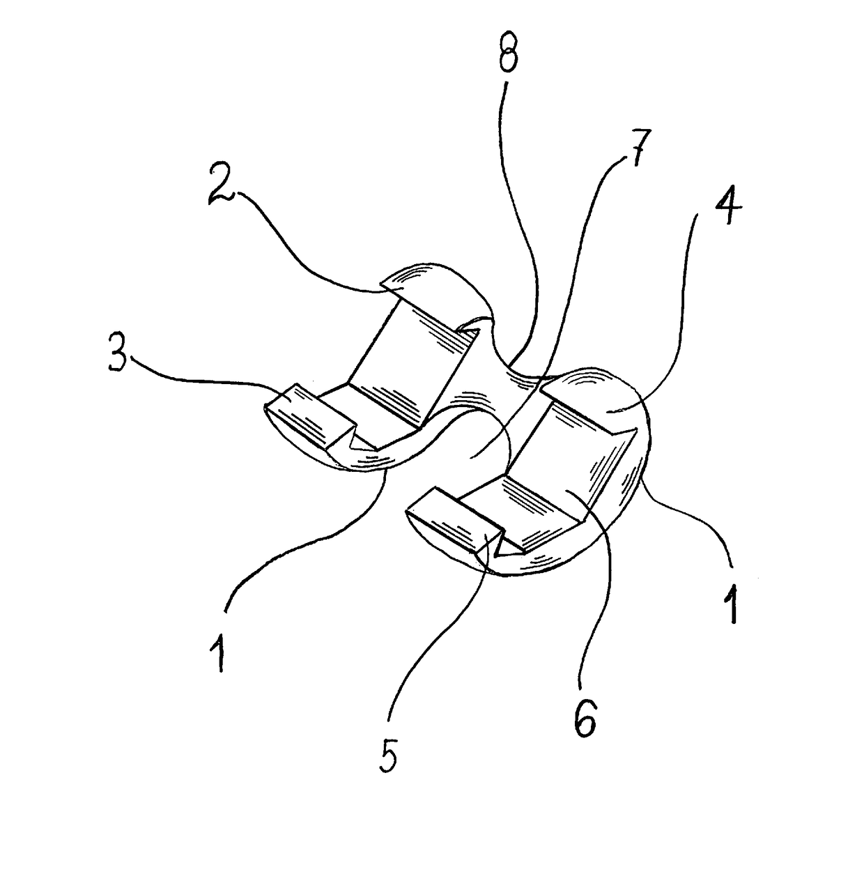
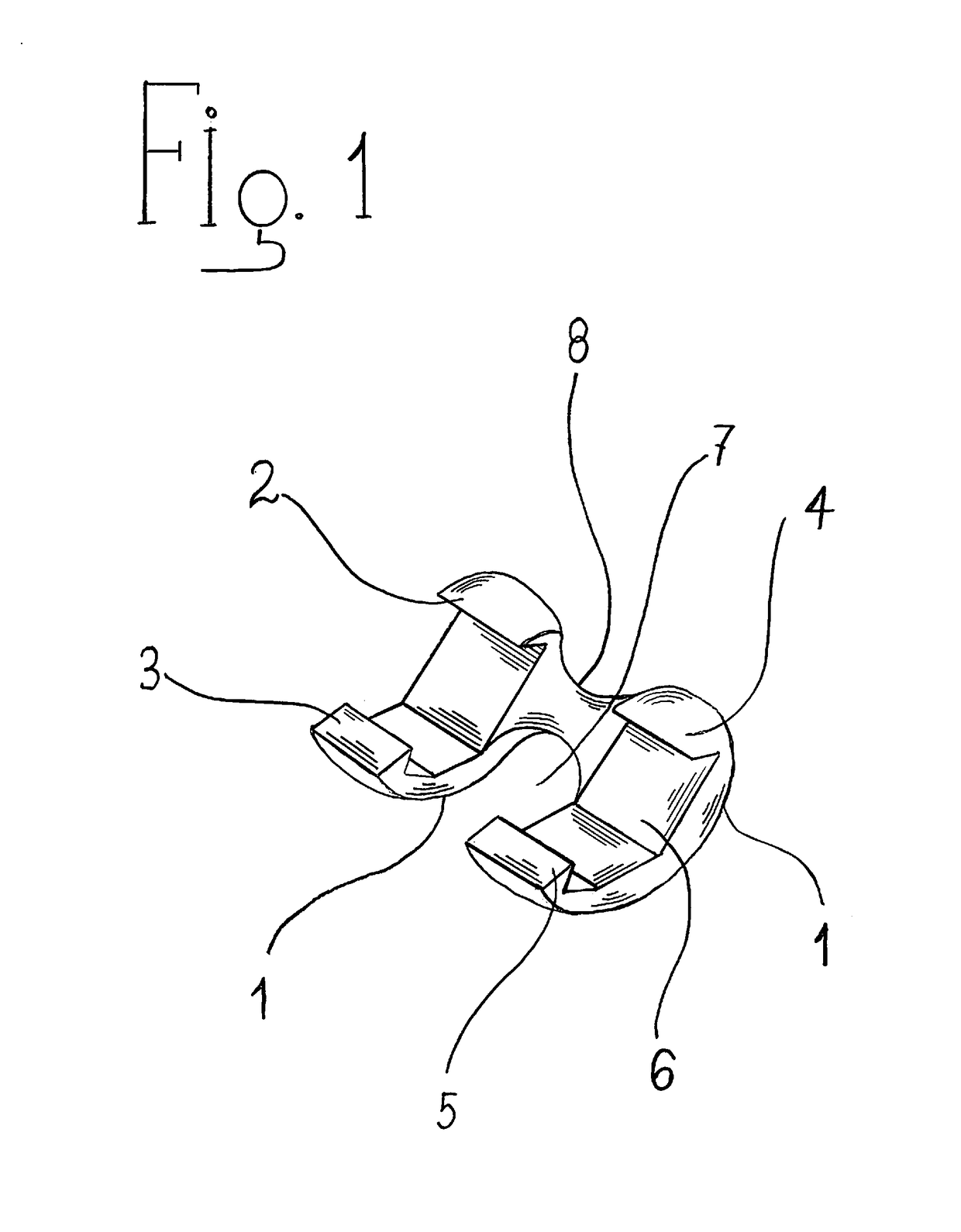
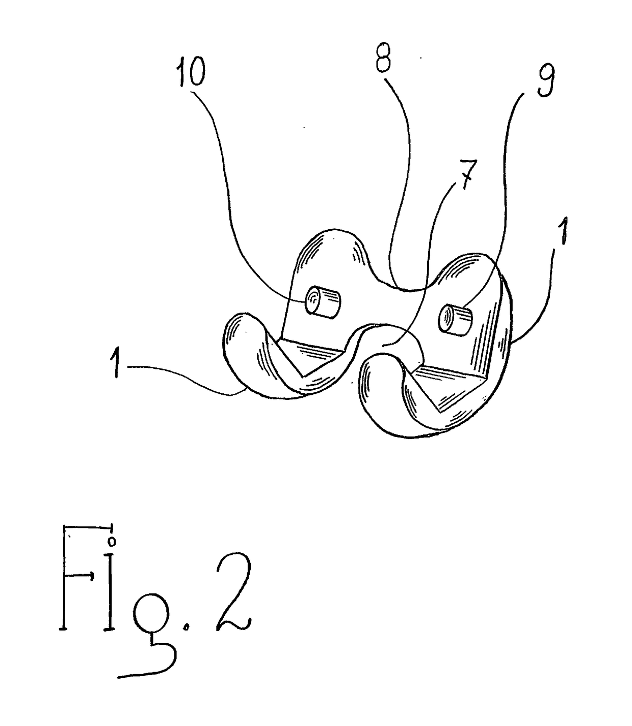
[0062]Turning now descriptively to the drawings, in which similar references characters denote similar element throughout the several views, the attached figures illustrate a concise bicondylar knee resurfacing prosthesis, which comprises a thin metallic femoral arcuate component, a metallic tibial tray and a polyethylene tibial insert. Furthermore, the present invention provides a detailed description of the method to insert the mini bicondylar implant through a small surgical incision made over the lateral aspect of the operated knee away from the patella and without any disruption or damage to the quadriceps muscle or the patellar tendon.

[0063]As opposed to conventional surgical total knee replacement surgery, where the patient lies supine on his back, the surgical technique utilized in the present invention is performed with patient lying on his side on the operative table. The operated knee placed onto a surgical platform 15 firmly attached to the side rails of the operative ta...


PUM


Abstract

A bicondylar knee implants with improved fixation means for resurfacing only the weight-bearing surface of the femoral medial and lateral condyles, while preserving the cruciate ligaments and avoids displacing the patella. The inventive device includes metallic convex articular surfaces for resurfacing the medial and lateral femoral condyles, and concave multifacial non-articular surfaces to be affixed to the resected distal surfaces of the femur. The prosthesis provides claws situated at the anterior and posterior ends of the medial and lateral metallic condyles, which will firmly attach the implant against the resected femoral condyle. The prosthesis is designed to be implanted through a direct lateral approach and does not resurface the femoropatellar joint. Furthermore, a minirobot or electromechanical actuator is used to perform the femoral and tibial bone cuts using electromagnetic bone chipper.

Description


Claims


Application Information

Patent Timeline
Owner JOINT INNOVATION TECH LLC
Learn More