Lens cap for a transistor outline package

Active Publication Date: 2017-10-12
SCHOTT AG
View PDF6 Cites 10 Cited by
  • Summary
  • Abstract
  • Description
  • Claims
  • Application Information

AI Technical Summary

Benefits of technology

[0040]In a lens cap having a thinned area according to the invention, mechanical stress in the regions of the lens edge and/or the lens stem is advanta

Problems solved by technology

For smaller packages, however, it is difficult with increasing miniaturization to provide a sufficiently stable bond between the lens and the shell without risk for the lens of being blasted off when the shell is subjected to mechanical stress, for example when the TO package is mounted or when the lens cap is assembled.
T

Method used


Image

  • Lens cap for a transistor outline package
  • Lens cap for a transistor outline package
  • Lens cap for a transistor outline package

Examples


first embodiment

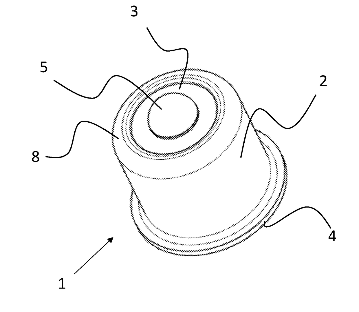
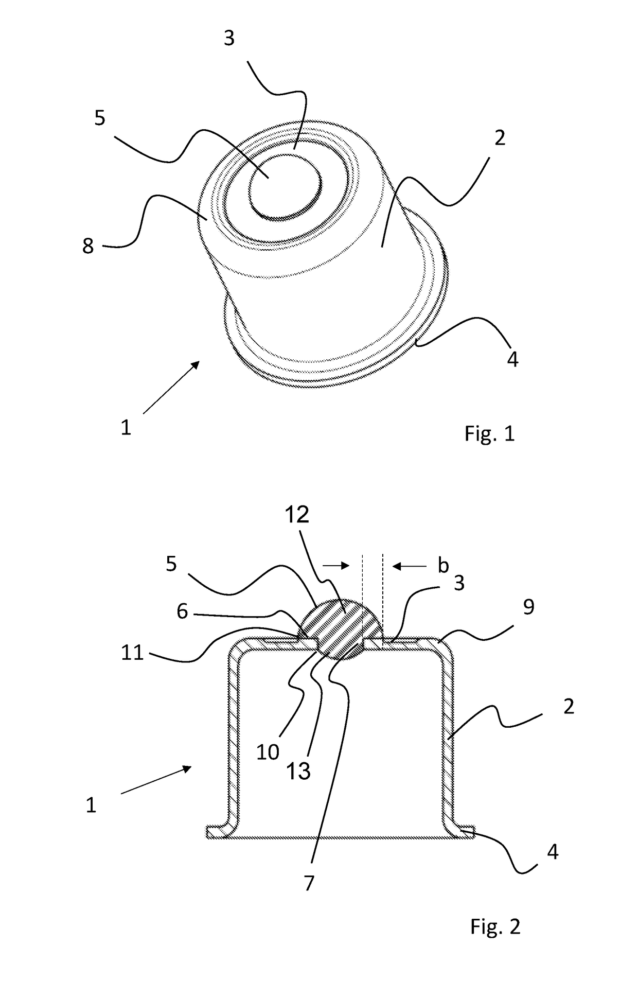
[0048]FIG. 1 is a perspective view illustrating a lens cap 1 according to the invention.

[0049]Lens cap 1 has a cup-shaped design and comprises a metal shell 2 of essentially circular cylindrical shape with a base wall 8 comprising a lens 5 arranged in the center thereof.

[0050]At a lower end, the metal shell 2 has a collar 4 via serves to secure the shell to the header of a TO package (not shown).

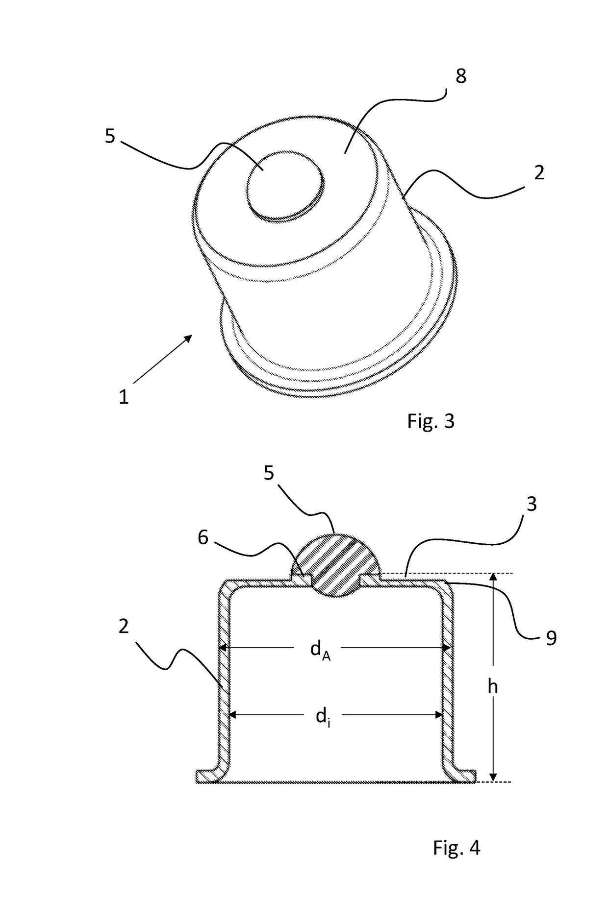
[0051]Metal shell 2 has an inner diameter and a height of less than 4 mm. A ratio of height to width of the shell is preferably between 7:3 and 3:7.

[0052]The wall thickness of the metal shell 2 is preferably less than 0.2 mm, more preferably less than 0.15 mm.

[0053]Already in this view it can be seen that an annular thinned area 3 in the form of a groove is provided around the lens 5, which serves to reduce stresses in the area of the lens 5, in particular in the area of lens edge 11.

[0054]FIG. 2 is a sectional view of FIG. 1.

[0055]It can be seen that the metal shell 2 has a reduced thicknes...


PUM


Abstract

A lens cap for a transistor outline (TO) package is provided that has an inner diameter of less than 4 mm. The lens cap includes a metal shell with a wall thickness of less than 0.2 mm and a thinned area surrounding the lens so that in the thinned area the wall thickness is reduced by at least 35%.

Description

CROSS REFERENCE TO RELATED APPLICATION[0001]This application claims benefit under 35 U.S.C. §119(a) of German Patent Application No. 10 2016 106 366.5 filed April, 2016, the entire contents of which are incorporated herein by reference.BACKGROUND1. Field of the Invention[0002]The invention relates to a lens cap for a transistor outline (TO) package and to a TO package equipped with a lens cap. More particularly, the invention relates to a round metal package according to the TO-33 or TO-38 standard (according to JEDEC).2. Description of Related Art[0003]Transistor outline (TO) packages are known. They are available in various designs. Such a TO package for high-frequency applications comprising a lens cap is known from patent document DE 102 47 315 B4 (Schott AG), for example.[0004]Such hermetically encapsulated packages are in particular used to accommodate laser diodes and photodiodes. For this purpose, the package has a window which may in particular be designed in form of a lens...

Claims


Application Information

Patent Timeline
IPC IPC(8): H01L23/00H01L23/08H01L23/06H01L23/04
CPCH01L23/564H01L23/041H01L23/08H01L31/02325H01S5/02212H01L31/0203H01L23/06H01L23/043H01S5/02253
Inventor HETTLER, ROBERTECKER, REINHARDLINDNER-STETTENFELD, MARTINMITTERMEIER, GEORG
Owner SCHOTT AG
Why Eureka
Try Eureka