Internal combustion engine

a combustion engine and internal combustion technology, applied in the field of internal combustion engines, can solve the problems of increasing the weight the resistance of moving the cylinder block, and the overall size of the combustion engine, so as to reduce the sliding resistance, reduce the enlargement of the internal combustion engine, and reduce the weigh

Inactive Publication Date: 2017-10-19
TOYOTA JIDOSHA KK
View PDF3 Cites 0 Cited by
  • Summary
  • Abstract
  • Description
  • Claims
  • Application Information

AI Technical Summary

Benefits of technology

[0009]According to the internal combustion engine according to this aspect of the present invention, by just making a single control shaft rotate, it is possible to make the cylinder block move relative to the crankcase through the coupling members. For this reason, a single control shaft need only be arranged at just one side of the left and right of the internal combustion engine and as a result the block movement mechanism can be arranged at just one side of the left and right of the internal combustion engine. Accordingly, there is no need for providing eccentric shafts at the two sides of the internal combustion engine like in the conventional internal combustion engine explained above. Further, there is no need to place a drive shaft for making the two eccentric shafts rotate. It is possible to suppress the enlargement of an internal combustion engine provided with a cylinder block able to move relatively to a crankcase and thereby keep down the increase in weight.
[0010]Further, when arranging the block movement mechanism at only one side of the left and right of the internal combustion engine, a block rotating force trying to make the cylinder block rotate to the block movement mechanism side is generated. For this reason, by supporting the side surface of the cylinder block at which the block rotating force acts by a support member, compared with the case of pushing against the side surface of the cylinder block at which the block rotating force acts by a pushing member, even if reducing the pushing force of the pushing member, it is possible to keep the cylinder block from tilting in a direction different from the direction of relative movement. Therefore, since it is possible to reduce the sliding resistance when moving the cylinder block, it is possible to keep the cylinder block from tilting in a direction different from the direction of relative movement while keeping down the load when moving the cylinder block.

Problems solved by technology

For this reason, there is the problem that the internal combustion engine becomes larger in size overall and the weight of the internal combustion engine increases.
However, the larger the pushing force by the pushing members, the greater the force by which the pushing members and support members clamp the cylinder block.
For this reason, there is the problem that the sliding resistance when moving the cylinder block becomes larger and the load when moving the cylinder block, that is, the load acting on the actuator, increases.

Method used


Image

  • Internal combustion engine
  • Internal combustion engine
  • Internal combustion engine

Examples


Embodiment Construction

[0025]Below, embodiments of the present invention will be explained in detail with reference to the drawings. Note that in the following explanation, similar component elements will be assigned the same reference notations.

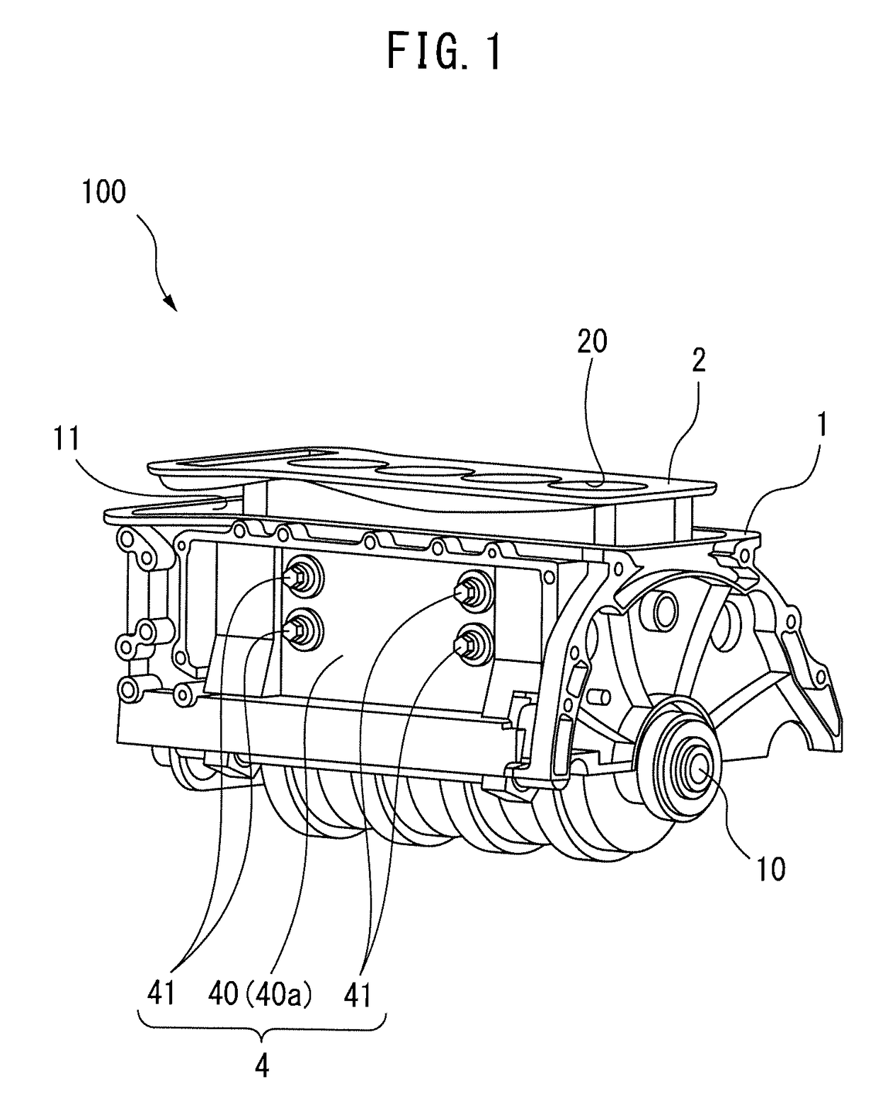
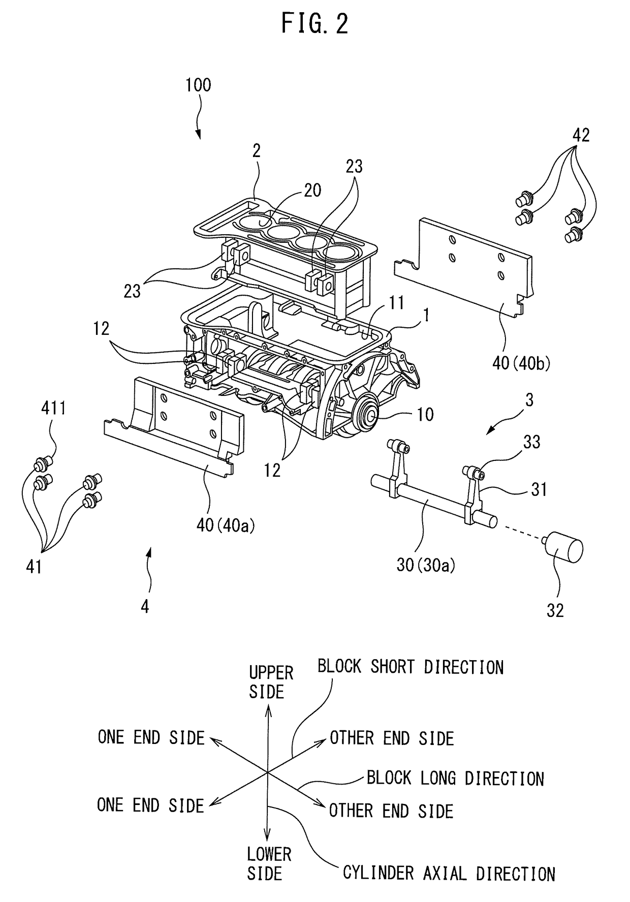
[0026]FIG. 1 is a schematic perspective view of an internal combustion engine 100 according to one embodiment of the present invention. FIG. 2 and FIG. 3 are respectively schematic disassembled perspective views of the internal combustion engine 100 shown in FIG. 1.

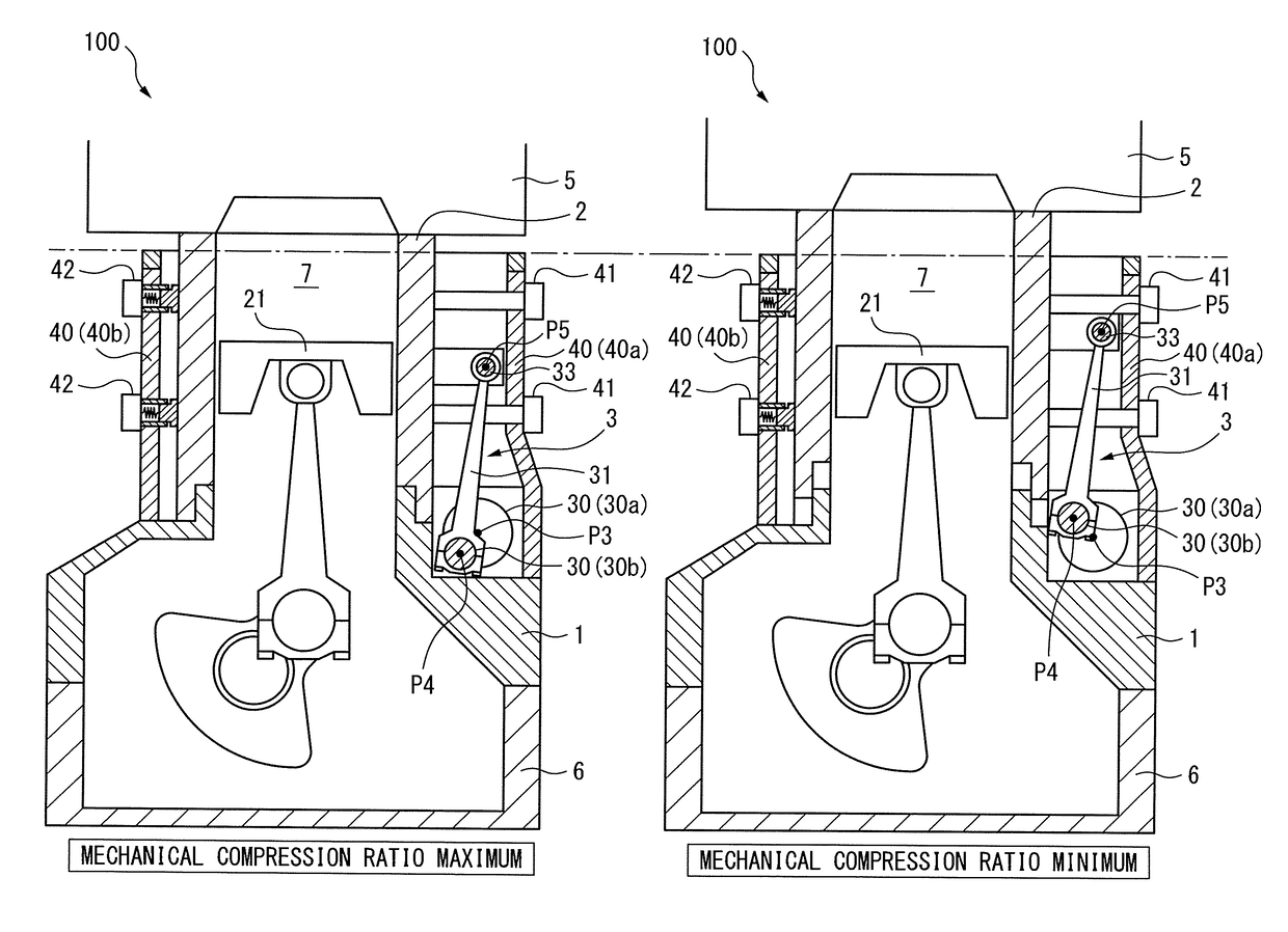
[0027]As shown from FIG. 1 to FIG. 3, the internal combustion engine 100 is provided with a crankcase 1, cylinder block 2, block movement mechanism 3, and guide mechanism 4.

[0028]The crankcase 1 supports a crankshaft 10 to be able to rotate and is provided with a block holding part 11 for holding the cylinder block 2 inside it.

[0029]The cylinder block 2 is made a separate member from the crankcase 1 so as to enable relative movement with respect to the crankcase 1. Part of it is held inside the block ho...


PUM


Abstract

An internal combustion engine provided with a cylinder block which can move relative to a crankcase is provided with a block movement mechanism arranged at just one side of the left and right of the internal combustion engine, a support member supporting a side surface of the cylinder block, and a pushing member pushing against a side surface of the cylinder block at the opposite side to the side surface supported by the support member. Further, the support member supports the side surface of the cylinder block at the side of arrangement of the block movement mechanism, while the pushing member pushes against the side surface of the cylinder block at the opposite side to the side of arrangement of the block movement mechanism.

Description

CROSS-REFERENCE TO RELATED APPLICATION[0001]This application claims priority based on Japanese Patent Application No. 2016-081381 filed with the Japan Patent Office on Apr. 14, 2016, the entire contents of which are incorporated into the present specification by reference.TECHNICAL FIELD[0002]Embodiments of the present invention relates to an internal combustion engine.BACKGROUND ART[0003]JP2012-219745A discloses as a conventional internal combustion engine provided with a cylinder block able to move relative to a crankcase, one provided with two eccentric shafts (cam shafts) arranged at the two sides of the internal combustion engine and one drive shaft made to rotate by an actuator and making the eccentric shafts rotate in opposite directions to each other to make the cylinder block move relatively. In this conventional internal combustion engine, further, to keep the cylinder block from tilting in a direction different from the direction of relative movement, one side surface of ...

Claims


Application Information

Patent Timeline
Patent Type & Authority Applications(United States)
IPC IPC(8): F02B75/04F02F7/00
CPCF02B75/041F02F7/0043
Inventor WATANABE, MASAKI
Owner TOYOTA JIDOSHA KK
Why Eureka
Try Eureka