Pair of spectacles adjustable depending on the pupillary distance of an individual

a technology of individual pupillary distance and adjustable pair, which is applied in the field of spectacle frames, can solve the problems of significant cost, significant delivery time, and significant impact on the user's experience, and achieve the effect of adjusting the pupillary distance and robust assembly

Inactive Publication Date: 2017-10-19
MAGNYS
View PDF2 Cites 0 Cited by
  • Summary
  • Abstract
  • Description
  • Claims
  • Application Information

AI Technical Summary

Benefits of technology

[0014]Thanks to the dispositions according to the invention, the adjustment of the position of the lenses may be very thin and adequate to the variation of the pupillary distance between the individuals. The holding of the lenses in position is ensured by the cooperation between the first and the second plurality of positioning elements, which also allows a robustness of the assembly adapted to the use of spectacles.
[0015]Furthermore, the displacement path of the lens along the curved line allows keeping the optimum optical correction for each position of the lens.

Problems solved by technology

A machining of custom-made lenses for each individual entails significant costs, affecting the user, and significant delivery times.
The adjustment of the position of the lenses therefore does not have an optimum accuracy.
Furthermore, considering the current manufacturing modes of optical lenses, a linear displacement of the lens relative to the frame results in a modification of the optical correction.

Method used


Image

  • Pair of spectacles adjustable depending on the pupillary distance of an individual
  • Pair of spectacles adjustable depending on the pupillary distance of an individual
  • Pair of spectacles adjustable depending on the pupillary distance of an individual

Examples


Embodiment Construction

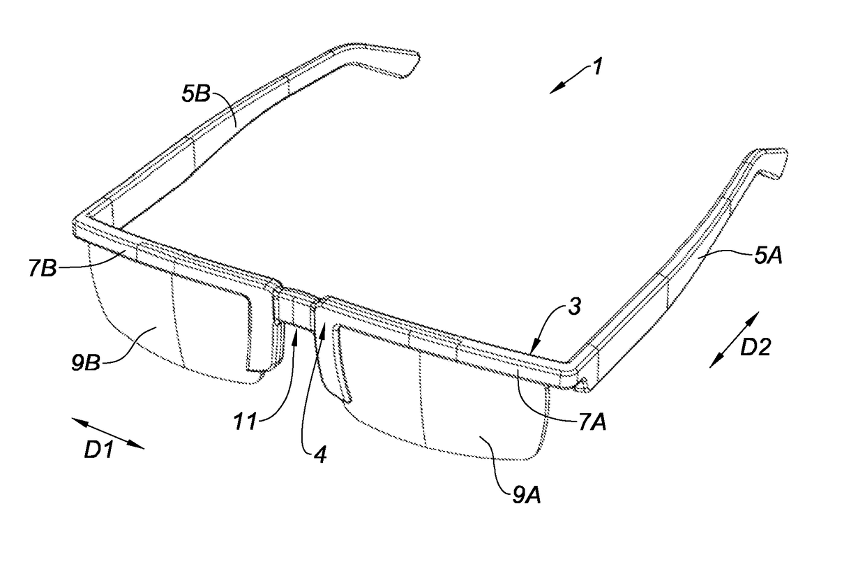
[0077]FIG. 1 represents a pair of spectacles 1 comprising a frame 3. The frame 3 comprises a front face 4 extending in an extension direction D1, a temple 5A and a temple 5B. In the use position, the temples 5A and 5B extend along an extension direction D2, transverse to the extension direction D1. The temple 5A is rotatably mounted around any of the ends of the front face 4 and the temple 5B is rotatably mounted around the other end of the front face 4.

[0078]The front face 4 comprises a receiving portion 7A of a lens 9A and a receiving portion 7B of a lens 9B. The front face 4 further comprises, between the receiving portions 7A, 7B of the lenses 9A, 9B, a bearing portion 11 intended to bear against the nose of a user.

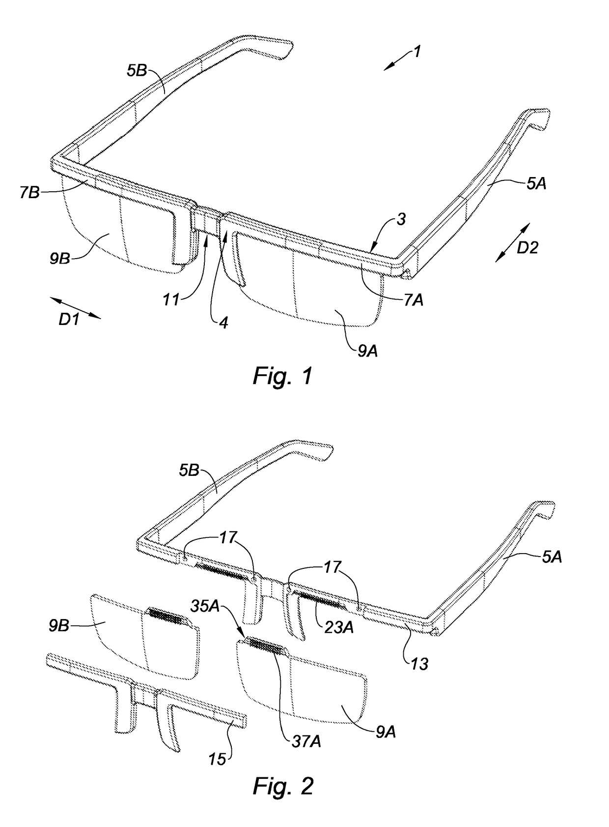
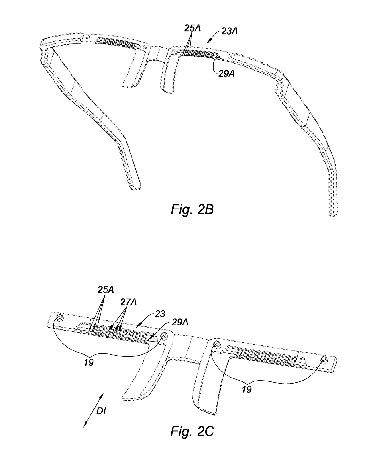
[0079]As represented in FIGS. 2a 2b and 2c, the front face 4 comprises two complementary parts. A first complementary part 13 is fastened to the temples 5a, 5b. A second complementary part 15 is intended to be fastened on the first complementary part 13 using compleme...


PUM


Abstract

The present invention relates to a spectacle frame comprising: a front face, on which the at least one lens is intended to be fastened; a first temple and a second adjusting device temple each attached on one end of the front face; and a first adjusting device intended to adjust the position of the at least one lens relative to the front face of the frame, the first adjusting device comprising at least one first positioning element intended to cooperate with at least one second positioning element of a second adjusting device belonging to the at least one lens, characterized in that the first adjusting device is arranged to define a set of relative positions of the at least one second positioning element relative to the frame disposed on a curved line comprised in an inclined plane relative to a reference plane comprising the optical axes in far vision of the eyes of a user. The present invention also relates to a spectacle lens.

Description

CROSS REFERENCE TO RELATED APPLICATIONS[0001]This application is a National Stage of PCT Application No. PCT / FR2015 / 052555 filed on Sep. 24, 2015, which claims priority to French Patent Application No. 14 / 59416 filed on Oct. 2, 2014, the contents each of which are incorporated herein by reference thereto.TECHNICAL FIELD[0002]The present invention relates to a spectacle frame and to at least one spectacle lens whose position is adjustable relative to the frame.BACKGROUND[0003]The pupillary distance of human beings may vary from a distance of up to ten millimeters from one individual to another. Usually, the lenses of the spectacles are adapted to the pupillary distance of each individual during machining. A machining of custom-made lenses for each individual entails significant costs, affecting the user, and significant delivery times.[0004]It is known in the state of the art to make spectacles whose lens position may vary relative to the frame. For example, the document U.S. Pat. No...

Claims


Application Information

Patent Timeline
Patent Type & Authority Applications(United States)
IPC IPC(8): G02C5/04
CPCG02C5/045G02C2200/22G02C2200/18G02C2200/08
Inventor THORAL, DENISLEPAGE, FRANCIS
Owner MAGNYS
Why Eureka
Try Eureka