
Ornament

a technology of ornaments and ornaments, applied in the field of ornaments, can solve the problems of insufficient ability to adequately sense fire, reduced perceived value of fire, and difficulty in achieving precision, and achieve the effects of smooth movement, stable pivoting, and easy visual perception

Inactive Publication Date: 2018-05-17
MARIND CO LTD
View PDF1 Cites 1 Cited by
  • Summary
  • Abstract
  • Description
  • Claims
  • Application Information

AI Technical Summary

Benefits of technology

The present invention provides an ornament that is highly visually appealing, allowing the jewelry within it to swivel and move freely in any direction. This movement creates a stable and long-lasting visual effect that increases the ornament's perceived value and attracts observers from various angles.

Problems solved by technology

For this reason, in situations where such movement or variation has been lacking, while the viewer of the ornament may have been able to sense the luster and / or brilliance of the ornament, there has been inadequate ability to adequately sense the fire thereof, and it has not always been the case that the beauty thereof was able to be brought forth to the desired agree and made manifest.
It has been hard to avoid situations in which visual attractiveness and decorativeness as an ornament have been impaired rather than enhanced, resulting in concern that the perceived value thereof may have been reduced.
However, with the aforementioned proposed personal accessory, it is difficult to achieve precision high enough to cause the contact region shape at the link to engage in line contact, and so what is substantially surface contact occurs instead.
For this reason, contact resistance has in practice been high, and it cannot be said that this has been sufficient for obtaining adequately repeatable swinging of the jewelry member.
For this reason, because the visually perceptible fire has been of low frequency and has been weak, and the swinging dies down almost immediately, it still cannot be said that this has been sufficient to permit the visual attractiveness and decorativeness inherent in the jewelry member to be brought forth to the desired agree and made manifest.
However, with this oscillating personal accessory, because the coupling and coupled fixtures both have arcuate or ring-like shapes, in the event that a force is applied thereto that would produce swinging that would exceed the angular range of a sloped surface relative to the suspended jewelry member, the part for suspending the jewelry member would itself, in that state and without swinging, slide in lateral fashion toward the front, toward the back, toward the left, or toward the right, as a result of which there are many restrictions on the direction in which the swinging may be applied, there is loss of the oscillatory energy that has been applied thereto, swinging does not occur, and so forth, and as many situations are observed in which swinging tends not occur, this has been inadequate as a personal accessory for causing swinging to occur in stable and continuous fashion.
In this way, because the frequency with which swinging occurs also decreases, the fire produced by the jewelry member becomes weaker overall, and due to the fact that the time over which swinging can be sustained is short and so forth, the situation has been such that the expected visual attractiveness and decorativeness have not been adequately manifested but have instead been impaired.
That is, due to the fact that the structure is such that the part for suspending the jewelry member and a retainer at the ornamental body are linked through surface contact or line contact, when the angle about which rotation occurs is large, there being a tendency for friction to occur, constraints become apparent as movement of the jewelry member is restricted.
This being the case, for a person visually perceiving the jewelry member of the ornament from a direction other than the front of the ornament, the fire produced by the jewelry member is difficult to notice; or if the fire can be noticed, from a direction other than the front, it will be found that it only lasts a short time before it disappears.
And even where, to address this, design has been carried out with the goal of producing fire by causing light incident thereon to be refracted in all directions as by cutting when the jewelry member is a diamond, because constraints on movement are large, it being difficult to appreciate the visual attractiveness and decorativeness thereof from a wide range of directions, it remains difficult to say that this has made it possible for the inherent visual attractiveness and decorativeness with which it is endowed to have been brought forth and made manifest.
This being the case, the directions in which oscillation can be imparted thereto are limited, and as rotation to the left and right is difficult, being unable to engage in rotation to the left and right, swinging in that direction is small and is not sustained.
Moreover, while fire generated by a jewelry member produced as a result of minute swinging can be visually perceived when the person who is visually perceiving the jewelry member is directly facing the jewelry member, difficulty occurs in attempting to visually perceive the luster, brilliance, and fire generated by the jewelry member when the person who is visually perceiving the jewelry member does not directly face the jewelry member but is viewing it from the side or from a diagonal direction, and so its visual attractiveness and decorativeness as oscillating personal accessory have not been adequately satisfactory.
For example, where the personal accessory is employed near the ear as is the case with an earring or stud earring, because the swinging member would be located to the side of the face, a person located in front of the wearer would likely find it difficult to directly face the jewelry member, and so one could not easily expect to be able to adequately catch sight of the fire.
As described above, with the ornaments having movable jewelry members that have been proposed to date, because oscillations are easily interrupted, because there is directionality to the directions in which swinging can occur, and because there is limited tendency to oscillate, the structure has not been such as to permit the luster, brilliance, and fire generated from the movable jewelry member to be visually perceived adequately and for a long time from a wide variety of directions in stable fashion, and from the standpoint of a structure permitting the desired visual attractiveness of the ornament to be manifested regardless of which direction it is viewed from, these have still not provided adequate satisfaction.

Method used


Image

  • Ornament
  • Ornament
  • Ornament

Examples


working example 1

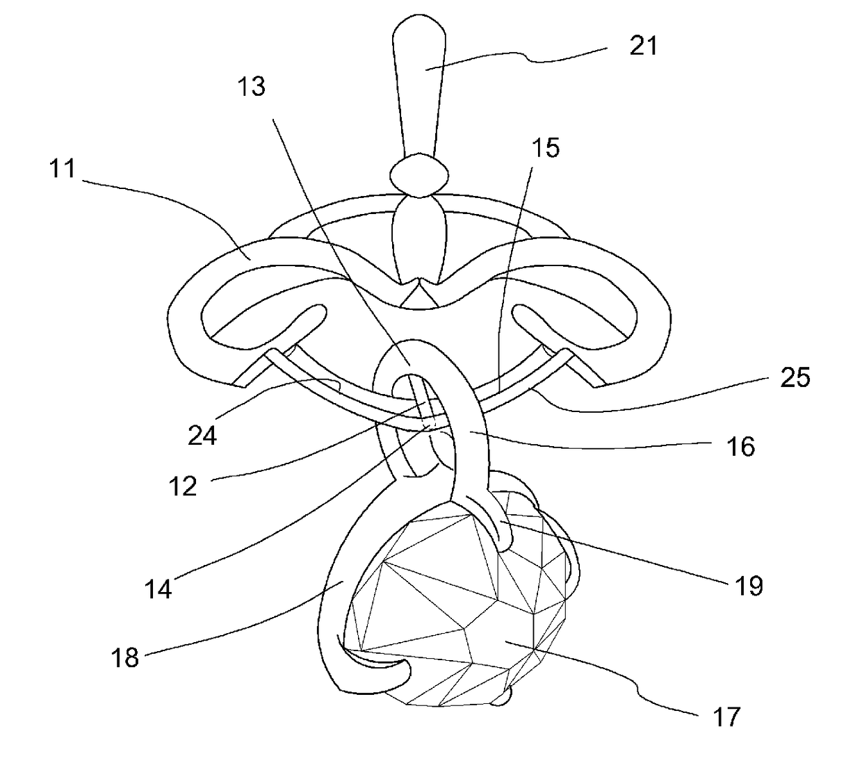
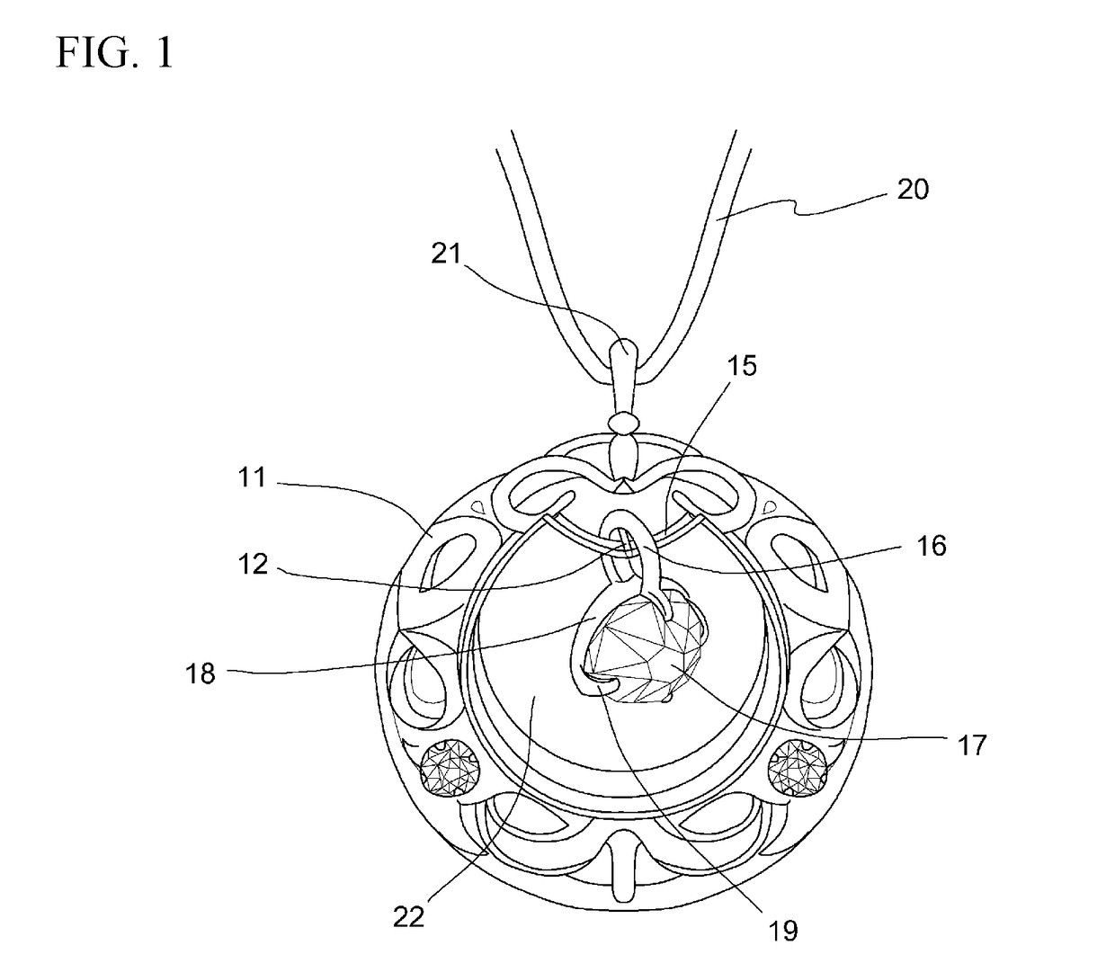
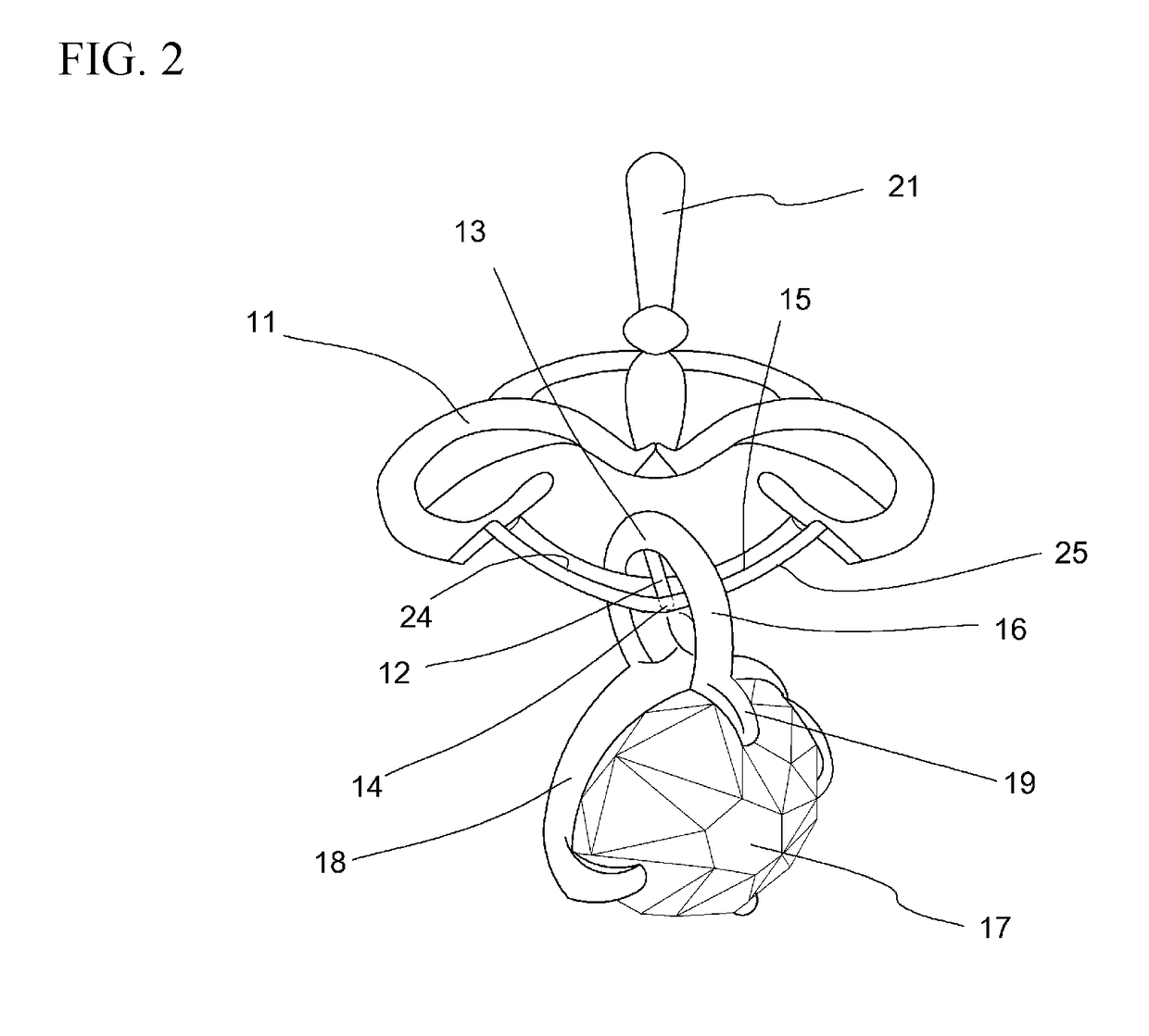
[0067]The ornament shown in FIG. 1 is a necklace having a pendant. The ornament body (11) is a pendant having a weight of approximately 1.1 g and a height such that the outside diameter thereof is 11 mm, the top end of the frame thereof which is made of 18-karat gold alloy having an opening in the form of a bail (21) through which a necklace is inserted, insertion of a necklace (20) of identical color which is made of 18-karat gold alloy through said bail (21) permitting this to be worn on the body. At Working Example 1, ornament body (11) is itself such that it also is of substantial decorativeness as a pendant, its external appearance, as shown in FIG. 1, being such that it is of cage-like shape, being provided with a central cavity (22), being engraved in patterns of intricate artisanship, and being decorated with small-carat diamonds slightly smaller than 1 mm at three peripheral locations thereon. In addition, in the vicinity of the top end of the central cavity (22) of ornamen...

working example 2

[0076]As the mode of another working example which is shown in FIG. 8, a constitution is shown in which a concave depression provided at the top central surface of a horizontal rod (23) provided at the upper portion of a cavity (22) in the ornament is made to serve as a receiving portion (15), a conical pivot shaft (12), the tip of which is the bottom end (14), being made to contact the receiving portion (15) at this location. Furthermore, FIG. 9 shows how the pivot shaft bottom end (14) makes contact with the receiving portion (15), and how as it does so it acts as pivot point about which the pivoting components pivot. FIG. 9 (a) shows the situation when at rest, and FIG. 9 (b) shows the situation when the pivot shaft is tilted to the left. At FIG. 9 (b), jewelry member (17) moves to the side opposite pivot shaft top end (13). In other words, at FIG. 9 (b), unlike FIG. 9 (a), when the height of the jewelry member (17) has moved to a location that is somewhat high, and pivot shaft t...


PUM


Abstract

An ornament has extremely high ornamental presentability, and can easily swing and move about freely in any direction in a manner that can be sustained for a long time, as a result of which visual perceptibility is increased to observers through repetitive variation in the direction of refraction and reflection at the jewelry member. The ornament has an ornament body provided with a receiving portion; a pivot shaft provided in erect fashion on, and in such manner that a bottom end portion thereof makes contact with, said receiving portion; a rigid suspending arm portion that protrudes from a top end portion of said pivot shaft; and a jewelry member supported in pendent fashion by a lower portion of said suspending arm portion; the ornament being characterized in that said pivot shaft is capable of pivoting freely about the bottom end portion thereof as pivot point on said receiving portion.

Description

TECHNICAL FIELD[0001]The present invention relates to an ornament having a jewelry member that is free to pivot.BACKGROUND ART[0002]Most earrings, broaches, necklaces, and other such ornaments are crafted using precious metals or other such materials that facilitate generation of luster. In addition, stratagems are employed at such ornaments to heighten visual attractiveness and decorativeness as an ornament, surfaces thereof being polished and also being imparted with complex shape or the like to constitute jewelry members and produce sensations of luster and / or brilliance in the viewer. And as one stratagem to further heighten visual attractiveness and decorativeness of a jewelry member in an ornament, the jewelry member of the ornament is such that precious metals or other such materials that facilitate generation of luster are employed in combination with gemstone(s). Known among the gemstones that may be employed here are those which, regardless of whether they are natural mate...

Claims


Application Information

Patent Timeline
Patent Type & Authority Applications(United States)
IPC IPC(8): A44C7/00A44C25/00
CPCA44C7/00A44C25/00A44C17/0275A44C25/001
Inventor OKADA, YASUHIRO
Owner MARIND CO LTD
Learn More