Image forming apparatus
a technology of forming apparatus and forming tube, which is applied in the direction of electrographic process apparatus, instruments, optics, etc., can solve problems such as transfer failure, and achieve the effect of greater unevenness
- Summary
- Abstract
- Description
- Claims
- Application Information
AI Technical Summary
Benefits of technology
Problems solved by technology
Method used
Image
Examples
first embodiment
[0140]To transfer a sufficient amount of toner onto the recesses of the uneven-surface sheet as a recording sheet P having a greater degree of unevenness (greater depth) than in the smooth sheet, the opposite-peak duty is preferably equal to or less than 50%. More preferably, the opposite-peak duty is less than 50%. With the opposite-peak duty of greater than 50%, the white spots due to the electric discharge and the secondary transfer failure occur. More specifically, with the opposite-peak duty of greater than 50%, the average potential Vave is shifted toward the opposite-peak side by the amount that exceeds the duty of 50% to reduce the absolute value of the average potential (time-averaged value) Vave, resulting in the occurrence of the secondary transfer failure. To avoid such a secondary transfer failure, if the peak-to-peak vale Vpp is increased to increase the average potential Vave, the transfer-peak value Vt increases, thereby increasing the possibility of occurrence of wh...
second embodiment
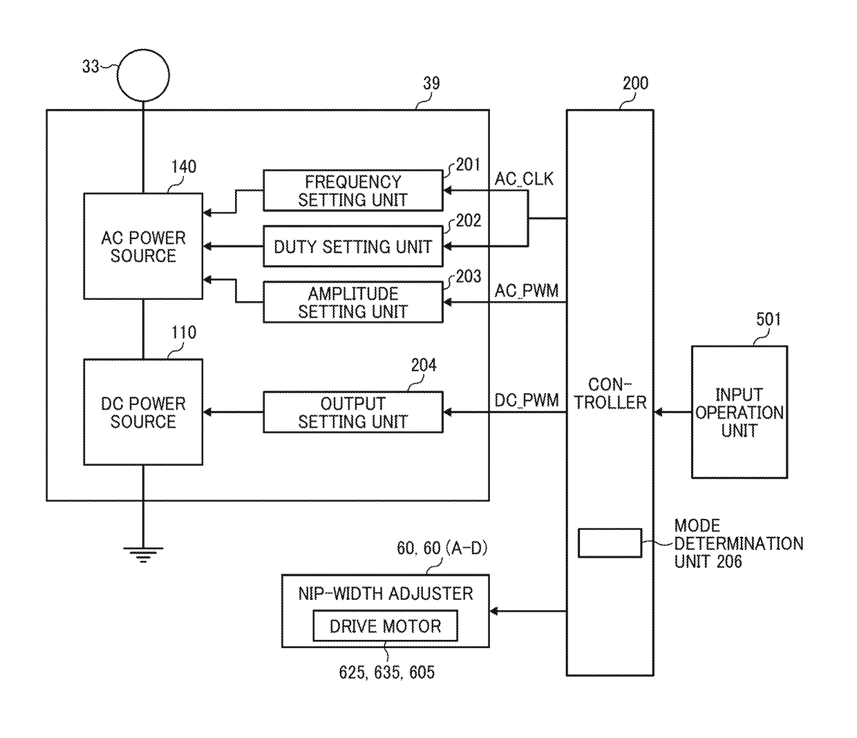
[0234]The image forming apparatus 1000 according to the present embodiment includes a mode selector 507 to select between a halftone-image priority mode to give a higher priority to image quality of a halftone image than to image quality of a solid image among images of a toner image, and a solid-image priority mode to give a higher priority to image quality of a solid image than image quality of a halftone image.
[0235]The controller 200 performs the first mode (the high-duty mode) with the halftone-image priority mode selected by the mode selector 507, and performs the second mode (the low-duty mode) with the solid-image mode selected by the mode selector 507. In the same manner as in the first embodiment, the duty in the first mode is greater than the duty in the second mode, and the secondary-transfer nip width W in the first mode is greater than the secondary-transfer nip width W in the second mode. Note that the manners in which the controller 200 controls duty and the secondar...
third embodiment
[0273]The following describes the third embodiment and the experimental results according to the third embodiment. The present inventors have performed another experiment of printing a test image with different frequency, peak-to-peak value Vpp, and DC voltage value (target current value under constant current control) of the secondary-transfer bias. In the low-smooth mode, a black solid image was secondarily transferred onto the uneven surface sheet (i.e., LEATHAC 66). In the high-smooth mode, a blue halftone image (2 by 2) was secondarily transferred onto the OK Top Coat (smooth sheet) having a weight of 128 gsm. The results are represented in Table 2.
TABLE 2EXPERIMENT CONDITIONS / TEST NUMBER671213SHEETUNEVEN-LEATHACLOWLOWLOWLOWBIASSURFACE66DUTYDUTYDUTYDUTYSHEET260 kgRANKRANKRANKRANKTransferability3443.5in SurfaceRecessesLEATHACLOWLOWLOWLOWBIAS66DUTYDUTYDUTYDUTY215 kgRANKRANKRANKRANKTransferability3.554.54.5in SurfaceRecessesLEATHACLOWLOWLOWLOWBIAS66DUTYDUTYDUTYDUTY175 kgRANKRANKRA...
PUM
 Abstract
Description
Claims
Application Information
 - R&D
- Intellectual Property
- Life Sciences
- Materials
- Tech Scout
- Unparalleled Data Quality
- Higher Quality Content
- 60% Fewer Hallucinations
Browse by: Latest US Patents, China's latest patents, Technical Efficacy Thesaurus, Application Domain, Technology Topic, Popular Technical Reports.
© 2025 PatSnap. All rights reserved.Legal|Privacy policy|Modern Slavery Act Transparency Statement|Sitemap|About US| Contact US: help@patsnap.com


