Battery pack and heat dissipating holder

a battery cell and heat dissipation holder technology, applied in the field of batteries, can solve the problems of limited battery cell availability, inability to dissipate heat generated in the battery cell from the whole periphery, and inability to meet the needs of users, so as to achieve efficient dissipation of heat generated in the battery cell, high safety, and reduced temperature

Inactive Publication Date: 2017-10-19
SANYO ELECTRIC CO LTD
View PDF2 Cites 20 Cited by
  • Summary
  • Abstract
  • Description
  • Claims
  • Application Information

AI Technical Summary

Benefits of technology

[0014]the temperature increase can be reduced by efficiently dissipating the heat generated in the battery cells from their whole peripheries;
[0021]A battery pack of the present invention have the following features:
[0023]a high safety can be achieved by certainly preventing also the induction of a thermal runaway of a battery cell; and
[0024]the battery cells can be smoothly inserted into fixed positions in the heat dissipating holder and can be disposed at the fixed positions in the insulated state. That is because the battery pack of the present invention includes the following structure:
[0025]the heat dissipating holder includes a holder body having insertion holes and a thermally-conductive insulating rubber disposed in the insertion holes;
[0026]the thermally-conductive insulating rubber includes elastic pipes that are disposed on the inner surfaces of the insertion holes and are elastically pressed on the peripheries of the battery cells;

Problems solved by technology

However, disadvantageously, in the battery pack having this structure, the battery cells are stacked and a heat dissipating material is disposed among the battery cells, so that the whole peripheries of the battery cells cannot come into contact with the heat dissipating material and the heat generated in the battery cells cannot be dissipated from the whole peripheries.
Therefore, disadvantageously, available battery cells are limited to square cells, cylindrical cells are not available, and the battery cells cannot be disposed at fixed positions via a heat dissipating material.
However, when this battery pack has a structure where the battery cells are arranged in multiple rows and columns, disadvantageously, the heat cannot be conducted both in the row direction and in the column direction and the heat of all battery cells cannot be dissipated uniformly.
Disadvantageously, this battery pack cannot effectively prevent the induction of a thermal runaway of a battery cell because a heat dissipating material is not disposed among all battery cells.
In the battery pack having this structure, however, it is difficult to insert the battery cells into insertion holes and make the whole peripheries of the battery cells closely contact the inner surfaces of the insertion holes in a thermally coupled state.
Therefore, disadvantageously, the whole peripheries of the battery cells cannot closely contact the heat dissipating material and the generated heat cannot be effectively conducted to the heat dissipating material.
Especially, the cylindrical battery cells have a dimension error in a manufacturing process, and the insertion holes in the heat dissipating material also have a dimension error in the manufacturing process.
Therefore, the battery cells cannot be inserted in the state where the battery cells closely contact the insertion holes.
In this manufacturing process, the insertion holes in the heat dissipating material made of aluminum have a significant dimension error.
Therefore, the battery pack where cylindrical battery cells are inserted into the insertion holes can achieve a feature of disposing the battery cells at fixed positions, but cannot achieve the condition in which the battery cells are smoothly inserted into the insertion holes to provide an ideal thermally-coupled state.
Furthermore, since a metal such as aluminum having a high thermal conductivity is used as the heat dissipating material, adjacent battery cells cannot be disposed in an insulated state.
Therefore, in a battery pack where adjacent battery cells are interconnected in series, disadvantageously, an exterior can of the battery cells comes into contact with the heat dissipating material made of aluminum, and a large short-circuit current flows.

Method used


Image

  • Battery pack and heat dissipating holder
  • Battery pack and heat dissipating holder
  • Battery pack and heat dissipating holder

Examples


Embodiment Construction

)

[0064]Hereinafter, examples of the present invention are described with reference to the accompanying drawings. The following examples show battery packs for embodying the technical ideas of the present invention. The present invention is not limited to the following battery packs. In this description, members shown in the scope of claims are not limited to the members of the examples.

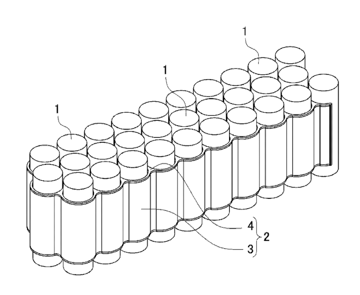
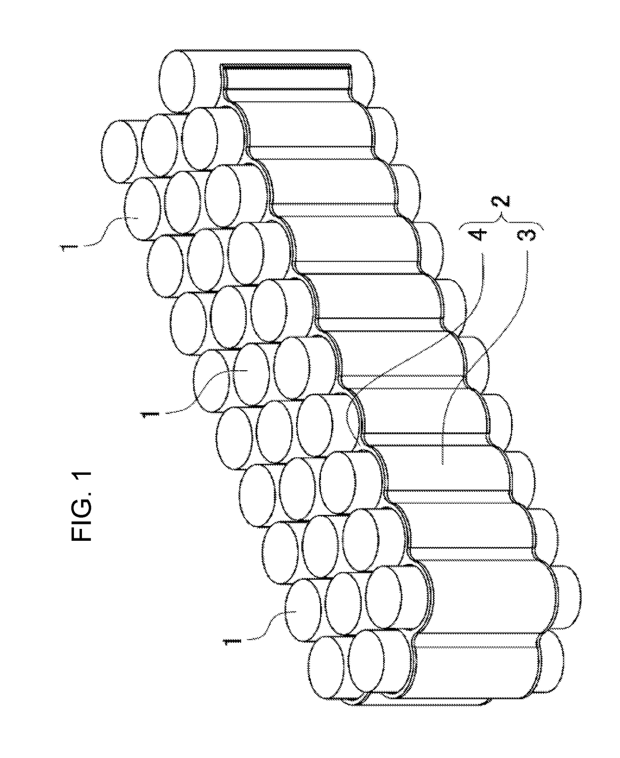
[0065]A battery pack shown in FIG. 1 includes a plurality of battery cells 1, and heat dissipating holder 2 in which battery cells 1 electrically interconnected in series and in parallel are disposed at fixed positions. Each battery cell 1 is a cylindrical lithium-ion secondary cell. As the cylindrical lithium-ion secondary cell, a cell frequently used as part number 18650 for various applications such as a laptop microcomputer, a bicycle, and an automobile can be employed. In the battery pack of the present invention, battery cell 1 is not limited to the cylindrical lithium-ion secondary cell. All ce...


PUM

PropertyMeasurementUnit
thicknessaaaaaaaaaa
thicknessaaaaaaaaaa
thermally-conductiveaaaaaaaaaa

Abstract

A battery pack includes: a plurality of battery cells (1); and heat dissipating holder (2) that is disposed among battery cells (1) and is in contact with the battery cells (1) in a thermally coupled state. Heat dissipating holder (2) includes: holder body (3) having insertion holes into which battery cells (1) are inserted; and thermally-conductive insulating rubber (4) having elastic cylinders to be disposed on the inner surfaces of the insertion holes. Each elastic cylinder includes a plurality of elastic projections projecting on its inner surface. The inner shape of each elastic cylinder in a non-insertion state of battery cell (1) is made smaller than the outer shape of battery cell (1). In heat dissipating holder (2), battery cells (1) inserted into the elastic cylinders are disposed at fixed positions in the insulated state. The elastic projections are elastically pressed on and closely contact the periphery of battery cell (1). The thermal energy of battery cells (1) is conducted to holder body (3) via the elastic cylinders.

Description

TECHNICAL FIELD[0001]The present invention relates to a battery pack including a plurality of battery cells disposed at fixed positions in a heat dissipating holder, and to the heat dissipating holder.BACKGROUND ART[0002]The chargeable capacity and output of a battery pack can be increased by increasing the number of battery cells. In a battery pack having a large charge / discharge capacity or a large output, many battery cells are interconnected in series, in parallel, or in series and in parallel. In this battery pack, by disposing, among the battery cells, a heat dissipating material such as aluminum having a high thermal conductivity, the heat of the battery cells can be conducted to the heat dissipating material and the temperature increase of them can be restricted. By forming the heat dissipating material in a shape where the battery cells are disposed at fixed positions, the heat dissipation is allowed in a state where the battery cells are disposed at the fixed positions.[00...

Claims


Application Information

Patent Timeline
Patent Type & Authority Applications(United States)
IPC IPC(8): H01M10/613H01M10/643H01M10/653H01M10/6555H01M50/213H01M50/224
CPCH01M10/613H01M10/6555H01M10/653H01M10/643H01M10/6551Y02E60/10H01M50/224H01M50/213
Inventor MURAKAMI, SATOSHITSUTSUMI, TAKUYA
Owner SANYO ELECTRIC CO LTD
Why Eureka
Try Eureka