Electrical power transfer switch

a technology of power transfer switch and switch body, which is applied in the direction of switch power arrangement, contact mechanism, contact form, etc., can solve the problems of inability to adapt to modification or multiple applications, the cost and size of power transfer switch in the past do not lend their application to light commercial or residential use, and the design of power transfer switch that has been used in the past is relatively difficult to assembl

Active Publication Date: 2017-10-26
HARTLAND CONTROLS LLC
View PDF1 Cites 11 Cited by
  • Summary
  • Abstract
  • Description
  • Claims
  • Application Information

AI Technical Summary

Problems solved by technology

Such transfer switches have worked well, but their cost and size did not lend their application to light commercial or residential use.
Some power transfer switches that have been used in the past have been relatively difficult to assemble.
Further, their design is not readily adaptable to modification or multiple application.
Also, it has been found that the assembly of transfer switches according to those designs was somewhat difficult and costly.
For example, in the designs of U.S. Pat. Nos. 6,538,223 and 8,735,754 the springs that spring bias the load contacts against the supply contacts have a relatively high spring force so that compressing the springs to form a finished assembly was difficult and required special tools or jigs.

Method used


Image

  • Electrical power transfer switch
  • Electrical power transfer switch
  • Electrical power transfer switch

Examples


Embodiment Construction

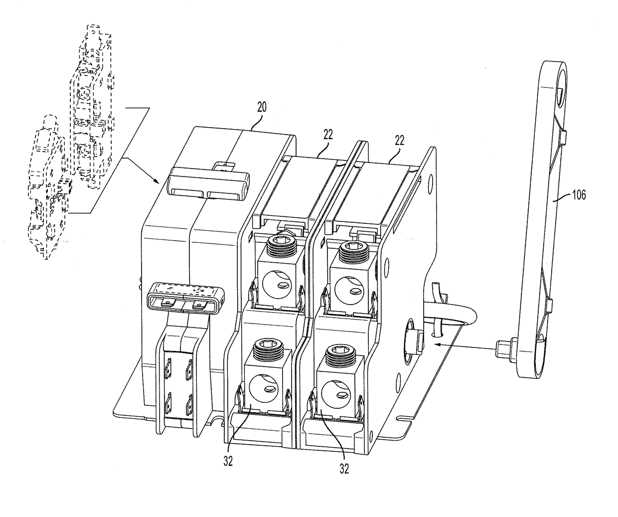
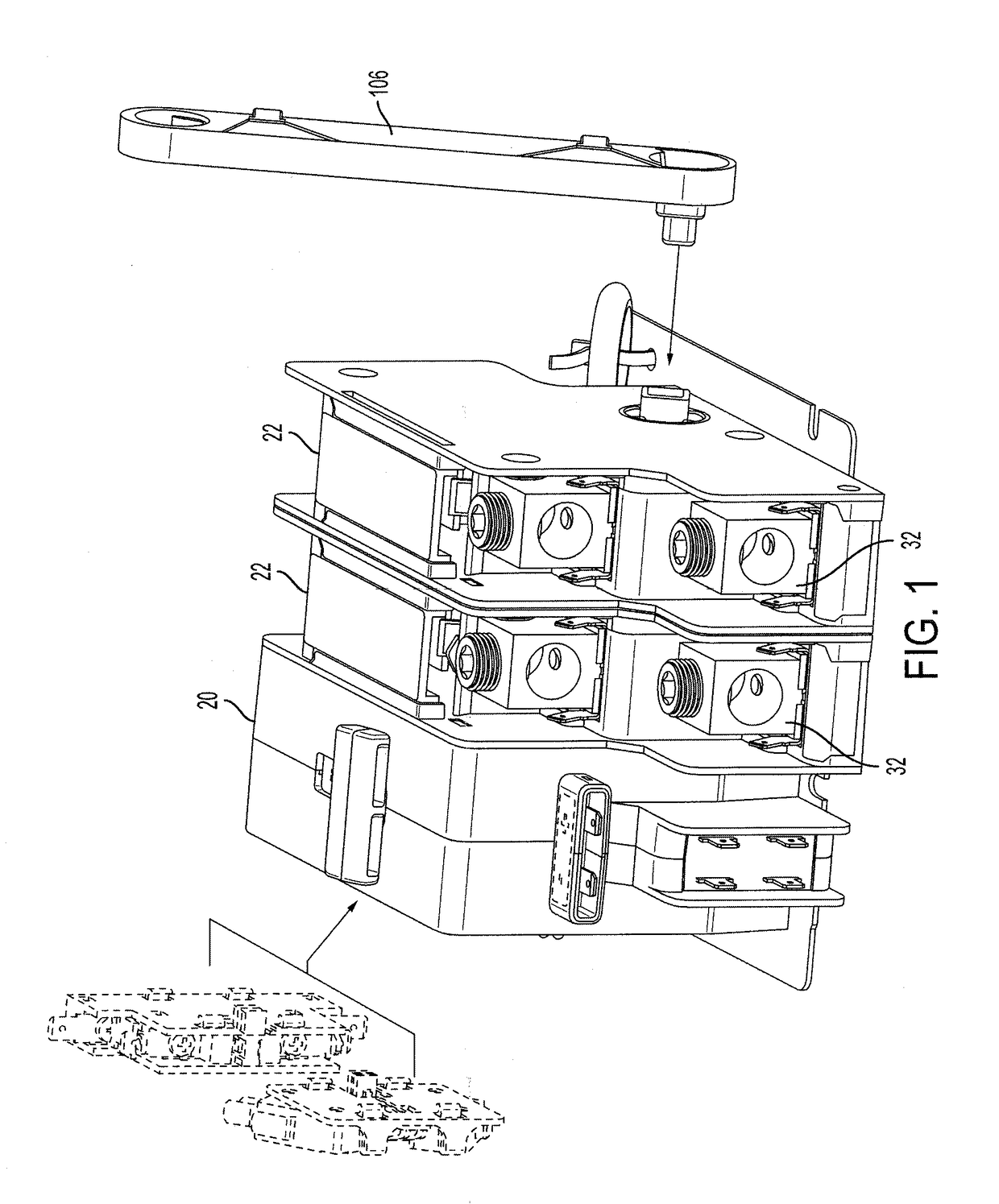
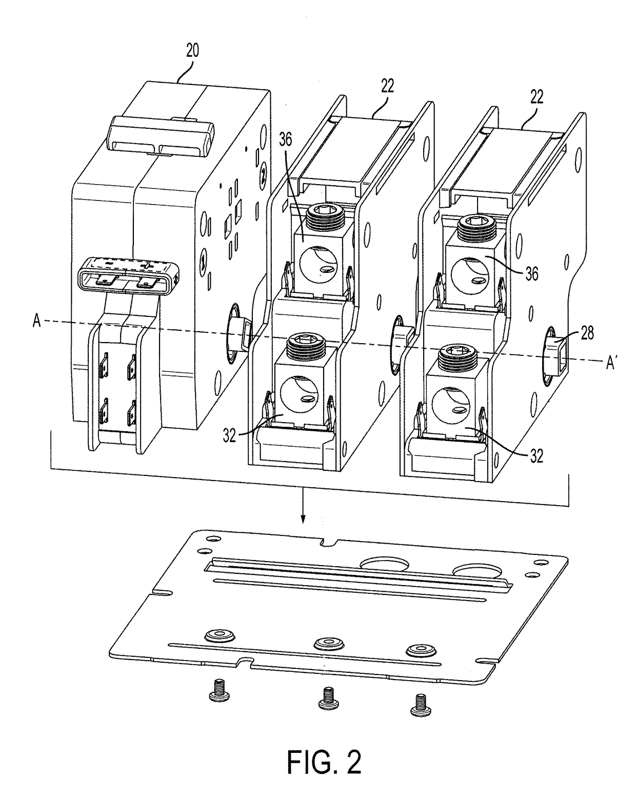
[0053]FIGS. 1-8 show a presently preferred embodiment of the disclosed invention that includes an actuator 20 and at least one transfer switch 22. Preferably, the disclosed invention includes more than one transfer switch 22 that are connected together in side-by-side relationship to form a linear array.

[0054]The actuator 20 controls the angular position of a driver 24 that is connected to the transfer switch 22 that is adjacent to the actuator 20. Each of the transfer switches 22 include respective drive linkage 26 that are connected together longitudinally along a common axis of rotation A-A′ such that the position of all of the transfer switches 22 is controlled by the position of the driver 24 in the actuator 20.

[0055]The drive linkage 26 in each of the transfer switches 22 is of a common design such that it can be connected together longitudinally in any order within the linear array. Preferably, drive linkage 26 has a first end such as a male end 28 and a second end such as a ...


PUM


Abstract

A modular transfer switch (22) and actuator (20) wherein multiple transfer switches are connectable in linear arrangement with the actuator such that the actuator controls the position of all of the transfer switches. Each of the transfer switches (22) includes a contact assembly (48) that converts over-rotation of the drive linkage (26) in the transfer switch to added pressure between the load contacts and the power contacts in the contact assembly.

Description

BACKGROUND OF THE INVENTION[0001]Field of the Invention[0002]The presently disclosed invention relates to electrical switches and, more particularly, electrical power transfer switches.[0003]Discussion of the Prior Art[0004]Electrical power transfer switches have been used to transfer an electrical load from one power source to another power source. Frequently, such switches are used in emergency panels that transfer incoming line power to an emergency generator or other source at times when the standard power source has been interrupted or failed due to inclement weather or other emergency conditions such as flooding.[0005]In the prior art, transfer switches have been developed to reliably and automatically switch industrial and commercial loads such as factories, shopping malls and hospitals to an alternate power source in the event of an electrical power failure. Many examples are known in the prior art.[0006]Such transfer switches have worked well, but their cost and size did no...

Claims


Application Information

Patent Timeline
Patent Type & Authority Applications(United States)
IPC IPC(8): H01H21/36H01H21/22
CPCH01H21/36H01H21/22H01H2203/036H01H2201/022H01H2205/002H01H2235/01H01H1/225H01H3/26H01H2001/545H01H2003/268H01H2009/265H01H2300/018
Inventor DIRKS, KEITHMOELLER, MATTHEWMCCLELLAND, MATHEW
Owner HARTLAND CONTROLS LLC
Why Eureka
Try Eureka