Automated functional tests for diagnostics and control

a technology of functional testing and diagnostics, applied in the field of control and diagnostic systems, can solve problems such as component malfunction typically determined, overall system may be subject to changes, and overall performance degradation

Inactive Publication Date: 2017-11-02
CARRIER CORP
View PDF13 Cites 29 Cited by
  • Summary
  • Abstract
  • Description
  • Claims
  • Application Information

AI Technical Summary

Benefits of technology

[0011]FIG. 2 is a flow chart of an exemplary HVAC control system;
[0012]FIG. 3 is a flow chart of an exemplary method of generating a model for HVAC system control;
[0013]FIG. 4 is a flow chart of another exempla...

Problems solved by technology

During long term operation, the components may be affected by malfunctions or the overall system may be subjected to changes that contribute to overall performance degradation.
However, a component malfunction is typically determined through an intensive labor effort that includes comparing normal operation data with data from a specific ti...

Method used


Image

  • Automated functional tests for diagnostics and control
  • Automated functional tests for diagnostics and control
  • Automated functional tests for diagnostics and control

Examples


Embodiment Construction

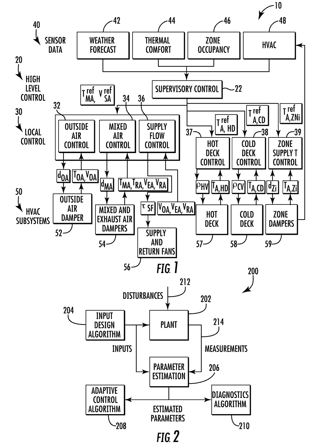
[0015]The following description relates to control and diagnostic systems such as, for example, building HVAC control and diagnostic systems, or cooling and heating plants. An objective of building HVAC control systems is to control thermal power generation and distribution to meet occupants' thermal comfort with the lowest possible energy costs. The thermal power generation may be accomplished utilizing components such as chillers and heating plants, and the distribution may be accomplished utilizing components such as air handling units (AHUs) and terminal units located in zones of the building. An objective of the building HVAC diagnostic systems is to detect and isolate faults associated with the HVAC equipment. An objective of the building HVAC fault-tolerant control system is to reconfigured the control system in real-time in order to accommodate the diagnosed faults as soon as they are detected, isolated, and characterized. The reconfiguration of the control system is accompl...


PUM


Abstract

In one aspect, a method of generating a model for HVAC system control is provided. The method includes generating a model of the performance of an HVAC system, providing the generated model to at least one of an optimal control system and a diagnostic system, and automatically tuning the HVAC system using the generated model and at least one of the optimal control system and the diagnostic system.

Description

STATEMENT REGARDING FEDERALLY SPONSORED RESEARCH OR DEVELOPMENT[0001]This invention was made with government support under contract number W912HQ-09-C-0056 awarded by the Army Aviation and Missile Command. The government has certain rights in the invention.FIELD OF THE INVENTION[0002]The subject matter disclosed herein relates to control and diagnostic systems and, more specifically, to building and HVAC control and diagnostic systems.BACKGROUND[0003]Building system controls may be based on mathematical representations of heat transfer for various components at different levels of the system. During long term operation, the components may be affected by malfunctions or the overall system may be subjected to changes that contribute to overall performance degradation. To efficiently control these components, control schedules need to be tuned and the health of the components needs to be estimated on a regular basis. However, a component malfunction is typically determined through an i...

Claims


Application Information

Patent Timeline
IPC IPC(8): F24F11/00G05B13/04
CPCF24F11/006G05B13/041F24F2011/0067F24F2011/0075F24F2011/0052G05B13/04G05B17/02G05B23/0243F24F11/38F24F11/74F24F11/54F24F2140/00F24F11/49F24F2120/00F24F11/32F24F11/62F24F11/46F24F11/30
Inventor BENGEA, SORINADETOLA, VERONICAKRUCINSKI, MARTINSARKAR, SOUMIKSRIVASTAV, ABHISKEKLOVETT, TEEMS E.MUKHERJEE, KUSHALGHOSH, ANARTACHEN, MEILI, PENGFEI
Owner CARRIER CORP
Why Eureka
Try Eureka