
Phase contrast microscope

a contrast microscope and phase technology, applied in the field of phase contrast microscopes, can solve the problems of increasing the cost of equipment, and the inability to perform high-accuracy adjustment, and achieve the effect of automatic adjustment of refraction and high accuracy, without increasing the cost or the size of the equipmen

Active Publication Date: 2017-11-09
FUJIFILM CORP
View PDF4 Cites 10 Cited by
  • Summary
  • Abstract
  • Description
  • Claims
  • Application Information

AI Technical Summary

Benefits of technology

The present invention is a phase contrast microscope that can automatically adjust the refraction of illumination light caused by the meniscus of a liquid surface in a container, without increasing cost or apparatus size. The microscope includes an adjustment optical system between the illumination optical system and the observation target, which is designed to adjust its optical characteristics based on the density of the captured image and its contrast. This allows for high accuracy in automatically adjusting the refraction of illumination light caused by the liquid surface shape.

Problems solved by technology

This leads an increase in cost and an increase in apparatus size.
In addition, in the case of controlling the focal power of the correction lens based only on the intensity of light detected by the light amount detection sensor, it is not possible to perform high-accuracy adjustment.

Method used


Image

  • Phase contrast microscope
  • Phase contrast microscope
  • Phase contrast microscope

Examples


Embodiment Construction

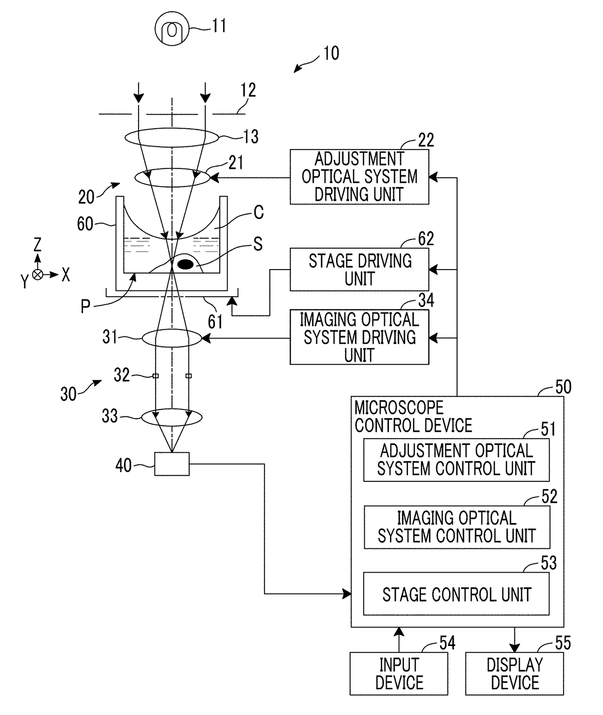
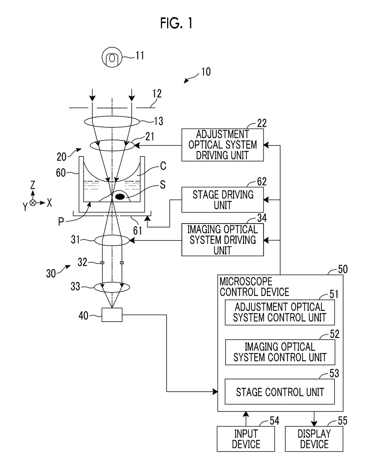
[0042]Hereinafter, a microscope system using an embodiment of a phase contrast microscope of the present invention will be described in detail with reference to the diagrams. FIG. 1 is a diagram showing the schematic configuration of the microscope system of the present embodiment.

[0043]As shown in FIG. 1, the microscope system of the present embodiment includes an illumination optical system 10, an adjustment optical system 20, an imaging optical system 30, an imaging unit 40, a microscope control device 50, an input device 54, and a display device 55. A stage 61 is provided between the adjustment optical system 20 and the imaging optical system 30, and a culture container 60 in which an observation target S is contained is provided on the stage 61. The microscope system of the present embodiment includes a stage driving unit 62 for moving the stage 61 in X and Y directions perpendicular to each other. The X and Y directions are directions perpendicular to each other on a plane par...


PUM


Abstract

The phase contrast microscope includes: an illumination optical system 10 that emits illumination light for phase difference measurement to an observation target placed in a container; an adjustment optical system 20 that is provided between the illumination optical system 10 and the observation target S, has at least one optical element 21, and adjusts refraction of the illumination light due to a liquid surface shape of a liquid C in the container 60; an imaging unit 40 that images the observation target to which the illumination light has been emitted; and an adjustment optical system control unit 51 that adjusts optical characteristics of the adjustment optical system 20 based on uniformity of a density of an image captured by the imaging unit 40 and a density contrast.

Description

CROSS-REFERENCE TO RELATED APPLICATIONS[0001]This application is a Continuation of PCT International Application No. PCT / JP2015 / 080688 filed on Oct. 30, 2015, which claims priority under 35 U.S.C §119 (a) to Japanese Patent Application No. 2014-238677 filed on Nov. 26, 2014. Each of the above application(s) is hereby expressly incorporated by reference, in its entirety, into the present application.BACKGROUND OF THE INVENTION1. Field of the Invention[0002]The present invention relates to a phase contrast microscope for performing phase difference measurement of an observation target in liquid.2. Description of the Related Art[0003]In recent years, phase difference measurement has started to be widely used as a method for observing transparent cultured cells, such as stem cells, achromatically. A phase contrast microscope is used as one that performs such phase difference measurement.[0004]In a general phase contrast microscope, ring-shaped illumination light is emitted to an observa...

Claims


Application Information

Patent Timeline
Patent Type & Authority Applications(United States)
IPC IPC(8): G02B21/14G02B21/36G02B21/02
CPCG02B21/14G02B21/36G02B21/025G02B3/14G02B21/086G02B21/361H04N23/56H04N23/672H04N23/673H04N23/74
Inventor MATSUBARA, KENTA
Owner FUJIFILM CORP
Learn More